A Nice Little Circuit
At time t = 0 , the switch closes. Prior to switch closing, the inductor and capacitors are de-energized. Let I R M be the maximum instantaneous value of the current flowing in the resistor between t = 6 and t = 1 0 .
Give your answer as ⌊ 1 0 0 I R M ⌋
Note: I R M is a positive number
![]()
The answer is 86.
This section requires Javascript.
You are seeing this because something didn't load right. We suggest you, (a) try
refreshing the page, (b) enabling javascript if it is disabled on your browser and,
finally, (c)
loading the
non-javascript version of this page
. We're sorry about the hassle.
2 solutions
@Karan Chatrath has posted a nice state-space solution already, but I will give my take on it too.
Fundamental equations for the three reactive elements:
V L = L I L ˙ I C 1 = C V C 1 ˙ I C 2 = C V C 2 ˙
Writing the non-dot quantities in terms of state variables ( I L , V C 1 , V C 2 ) gives:
V C 1 − V C 2 = L I L ˙ R V − V C 1 − I L = I R − I L = C V C 1 ˙ I L = C V C 2 ˙
In the first equation, the resistor voltage is a common-mode term which cancels.
The purpose of this formulation is to express the rates of change of the state variables in terms of the known present values of the state variables. Knowing the rates of change, we can use numerical integration to solve the differential equations.
![]()
Let the current flowing through the circuit be I r . This current splits into two branches. Let the current flowing through the branch with only a capacitor (branch 1) be I 1 and that flowing through the branch comprising of an inductor and a capacitor (branch 2) be I 2 .
I r = I 1 + I 2
Let the charge on the capacitor in branch 1 be Q 1 . Let the charge on the capacitor in branch 2 be Q 2 .
This implies:
Q ˙ 1 = I 1 Q ˙ 2 = I 2
Applying Kirchoff's voltage law to the circuit gives the following two equations:
− 1 0 + Q 1 + I 1 + I 2 = 0 − 1 0 + d t d I 2 + Q 2 + I 1 + I 2 = 0
Differentiating the first equation among the above two with respect to time gives:
I 1 + d t d I 1 + d t d I 2 = 0
Replacing d t d I 2 in the above expression yields:
I 1 + d t d I 1 + 1 0 − ( Q 2 + I 1 + I 2 ) = 0
Summarising the circuit equations:
Q ˙ 1 = I 1 Q ˙ 2 = I 2 I ˙ 1 = Q 2 + I 2 − 1 0 I ˙ 2 = − Q 2 − I 1 − I 2 + 1 0 I r = I 1 + I 2
These equations can be recast into a state-space form as shown below:
⎣ ⎢ ⎢ ⎡ Q ˙ 1 Q ˙ 2 I ˙ 1 I ˙ 2 ⎦ ⎥ ⎥ ⎤ = ⎣ ⎢ ⎢ ⎡ 0 0 0 0 0 0 1 − 1 1 0 0 − 1 0 1 1 − 1 ⎦ ⎥ ⎥ ⎤ ⎣ ⎢ ⎢ ⎡ Q 1 Q 2 I 1 I 2 ⎦ ⎥ ⎥ ⎤ + ⎣ ⎢ ⎢ ⎡ 0 0 − 1 1 ⎦ ⎥ ⎥ ⎤ V I r = [ 0 0 1 1 ] ⎣ ⎢ ⎢ ⎡ Q 1 Q 2 I 1 I 2 ⎦ ⎥ ⎥ ⎤
Using more convenient notation, the equations can be rewritten as:
x ˙ = A x + B V = f ( x ) I r = C x
Where x is a four-dimensional vector with components:
x = ⎣ ⎢ ⎢ ⎡ Q 1 Q 2 I 1 I 2 ⎦ ⎥ ⎥ ⎤ V = 1 0
This set of multivariable differential equations can be solved analytically. However, here, a numerical route is chosen. The initial value of x is: x ( 0 ) = ⎣ ⎢ ⎢ ⎡ 0 0 1 0 0 ⎦ ⎥ ⎥ ⎤
These initial values can be obtained by analysing the circuit at time t = 0 . The capacitors are discharged and the inductor is de-energised. I often mention in my solutions about using numerical methods without actually describing my approach. The simplest method of numerical integration is described as follows.
The circuit is simulated up to a time of t = 1 0 seconds in steps of 1 microsecond ( Δ T ). At a general time instant T , the derivative can be approximated as:
x ˙ ( T ) = f ( x ( T ) ) x ˙ ( T ) ≈ Δ T x ( T + 1 ) − x ( T ) = f ( x ( T ) )
x ( T + 1 ) = x ( T ) + f ( x ( T ) ) ( Δ T )
The above equation is iterated in a simple loop. This calculation has been done using a computer program.
Psuedo code :
for loop start T = 0 in steps of Δ T upto t = 1 0
x ( T + 1 ) = x ( T ) + f ( x ( T ) ) ( Δ T )
for loop end
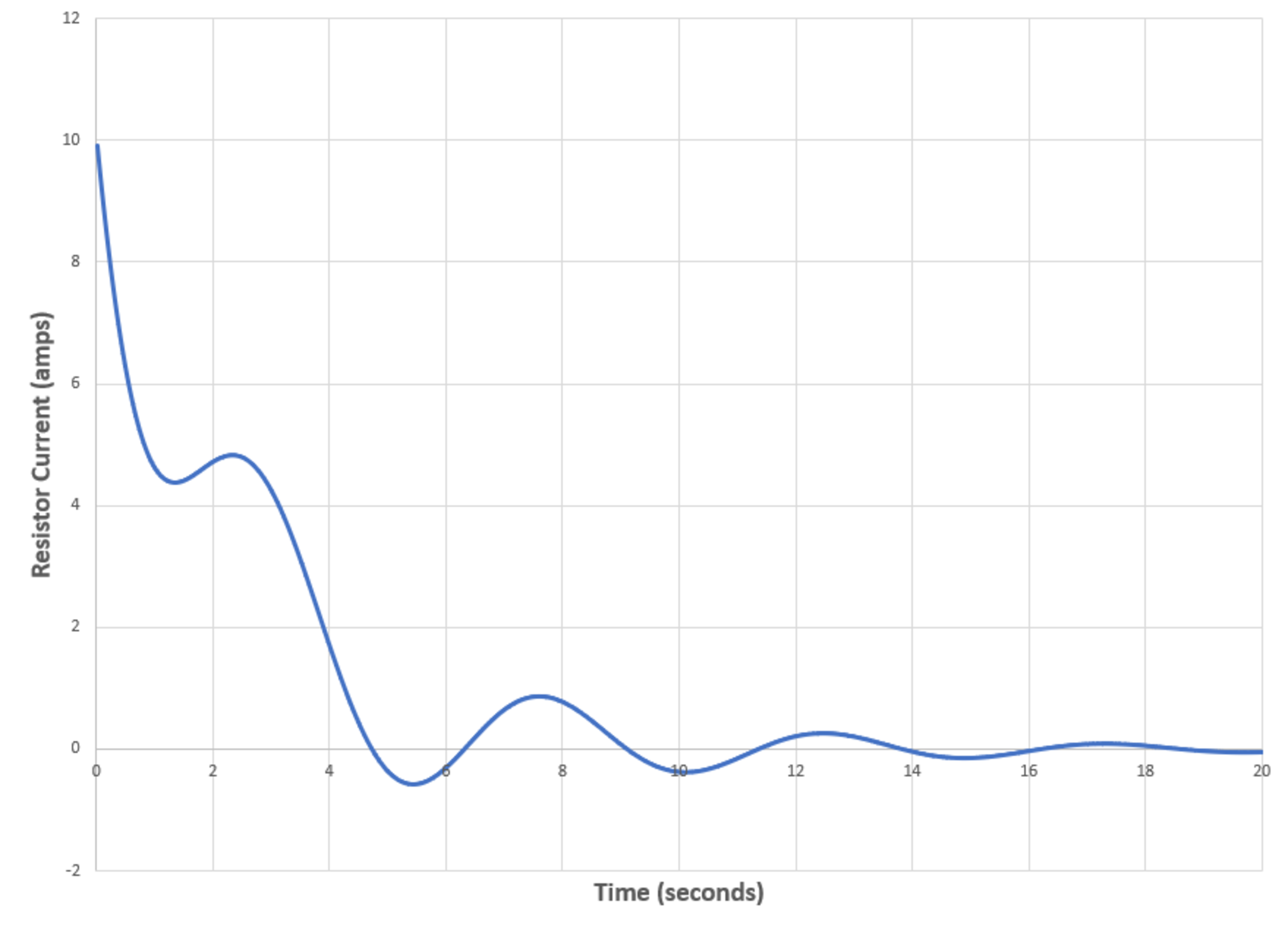
The result I r from 6 to 10 seconds can be studied in the following diagram.
Answer is: ⌊ 1 0 0 I r , m a x ⌋ = 8 6