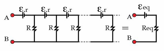
A very long circuit
A large number of AA batteries with emf E = 1 . 5 V and resistors with resistance R form an infinite circuit, as shown in the figure. The internal resistance of the batteries is r . Thevenin's theorem tells us that this infinite circuit can be replaced by a single source with emf E eq , connected in series with an equivalent resistor R eq . Determine the equivalent emf E eq in volts if R r = 2 1 .
The answer is 3.
This section requires Javascript.
You are seeing this because something didn't load right. We suggest you, (a) try
refreshing the page, (b) enabling javascript if it is disabled on your browser and,
finally, (c)
loading the
non-javascript version of this page
. We're sorry about the hassle.
3 solutions
@Derek Khu you should have explained with a diagram. I 🙋 find it difficult to comprehend what you want to ELABORATE. A labelled(neat) could have made pretty ✨👩✨easy to grasp.
Let R = 2 and r = 1 , by Thevenin's theorem,
1 . 5 V with 3 →
2 . 1 V with 2 . 2 →
2 . 5 V with 2 2 1 1 →
2 3 4 2 5 V with 2 8 5 1 →
2 2 2 1 9 V with 2 3 4 1 1 …
Tells that 3 V with 2 such that 3 V with R is the eventual situation. However, the situation cannot last for long as the current is running even with no external circuit to connect for loading. Current for each step of connection for rough visulization is 2 2 . 1 − 1 . 5 , 2 2 . 5 − 1 . 5 , 2 2 3 4 2 5 − 1 . 5 , 2 2 2 2 1 9 − 1 . 5 and etc, batteries with higher current shall exhaust earlier. Other than for questioning and answering, the combination of circuits shall not be applied in practice as a source of power supply.
Answer: 3
V 0 = 1 . 5 V and R 0 = 3
V 1 = R 0 + 2 1 . 5 R 0 + 2 V 0 + 3 and R 1 = 1 + 1 + R 0 2 2
V ∞ = 3 V and R ∞ = 2 = R {Simulation using Excels reveals that 50 terms for 15 S.F. turns into all integers.}
Look at the figure, the close loop E e q , R e q and R :
I = R e q + R E e q I = 2 R E e q
Such that, the flanking the resulting voltage resistance R is
E = I × R
E = 2 E e q
This implies the voltage of
A B = E q
E q = e + E
E e q = e + 2 E e q E e q = e × 2 E e q = 1 . 5 × 2 = 3
Let us begin by finding the equivalent resistance
R
e
q
. We claim that this resistance depends only on
r
and
R
. In other words,
R
e
q
=
f
(
r
,
R
)
.
R
e
q
cannot depend on
E
because of dimensional analysis. Note that there's no way to combine
E
with
r
and
R
to form a quantity with dimension of resistance. Also, note that this remark works because there's "only one emf"
E
in the circuit. Otherwise, the equivalent resistance
R
e
q
could depend on
E
1
/
E
2
,
(
E
1
/
E
2
)
2
…
etc.
Since
R
e
q
does not depend
E
we can determine it by simply setting
E
=
0
.
Then, the circuit reduces to the classic infinite ladder with resistors
r
and
R
. The standard method to solve this problem is the following. We add one more section (
r
and
R
resistors) and note that the circuit is still the same infinite circuit (see the figure below).
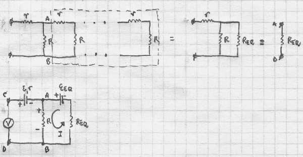
Then R e q + R R e q R + r = R e q → R e q = 2 r ( 1 + 1 + r 4 R ) . Now, we repeat the same trick. We add an extra section, this time with a nonzero E . The voltage between the points C and D must be E e q . Using Kirchhoff's laws we write E e q = E + E e q R + R e q R → E e q = E ( 1 + R e q R ) = 2 E ( 1 + 1 + r 4 R ) = 3 V .
@David Mattingly what happens when all the emf's are different or not equal, like they are related to the previous ones for example they form a decreasing GP or something like that
We need to first simplify that infinite circuit. One way of simplifying it is of course to make it equivalent to the diagram on the right in the question (the "Thevenin equivalent circuit"). Another way is to retain the leftmost AA battery as well as the leftmost resistor, and then convert the remaining infinite circuit to the Thevenin equivalent circuit. With two ways of representing that same infinite circuit, we can try to form equations regarding the overall resistance and potential difference of the two circuits. Call the Thevenin equivalent circuit "Circuit X" and the other simplified circuit "Circuit Y".
We first find the resistance of the two circuits between points A and B. Circuit X obviously has resistance R e q between A and B. Circuit Y consists of two resistors in parallel, and given that R = 2 r , their overall resistance is 2 r + R e q 2 r R e q . So the resistance between A and B is r + 2 r + R e q 2 r R e q . So we have r + 2 r + R e q 2 r R e q = R e q . This is actually a quadratic equation in R e q and we can solve it to obtain R e q = 2 r .
Now we shall find the potential difference of the two circuits between points A and B. Circuit X obviously has a potential difference of E e q . It is a little trickier for Circuit Y. We first ignore the AA battery and look at the potential difference between A and B. We can see that the resistors with resistances R and R e q essentially form a "voltage divider", and we're measuring the potential difference across the resistor with resistance R . Since R = R e q as calculated earlier, we have this potential difference as 2 1 E e q . But we should not forget the AA battery, so the potential difference between A and B in Circuit Y is 2 1 E e q + E . So we get the equation E e q = 2 1 E e q + E , which is easily solved to give E e q = 2 E = 3 V .