AC Current Measurement
Suppose we apply 1 volt RMS (root mean squared) at 60 Hz across a series RL (resistor-inductor) load.
Using an AC ammeter, we measure a current through the load with an RMS magntitude of 2 1 amperes, which lags the source voltage by 45 degrees.
We then apply 1 volt RMS at 120 Hz across the same load. What RMS current magnitude will the ammeter measure in this case?
Give your answer to 3 decimal places.
Assume that we neglect the skin effect .
The answer is 0.447.
This section requires Javascript.
You are seeing this because something didn't load right. We suggest you, (a) try
refreshing the page, (b) enabling javascript if it is disabled on your browser and,
finally, (c)
loading the
non-javascript version of this page
. We're sorry about the hassle.
3 solutions
Nicely done but doesn't deserve to be level 5
Let the source voltage to have a phase angle of 0 and the impedance of the load be Z = R + ω L i , where ω = 2 π ( 6 0 ) is the angular velocity of the alternating current.
Then, the current through the load:
I Z V 1 ∠ 0 ∘ ⟹ Z R + ω L i = 2 1 ∠ − 4 5 ∘ = 2 1 ∠ − 4 5 ∘ = 2 Z ∠ − 4 5 ∘ = 2 ∠ 4 5 ∘ = 1 + i
When frequency is raised from 60 Hz to 120 Hz, we have Z 1 = R + 2 ω L i = 1 + 2 i , and:
I 1 ⟹ ∣ I 1 ∣ = Z 1 V = 1 + 2 i 1 = 5 1 − 2 i = ∣ ∣ ∣ ∣ 5 1 − 2 i ∣ ∣ ∣ ∣ = 5 5 ≈ 0 . 4 4 7
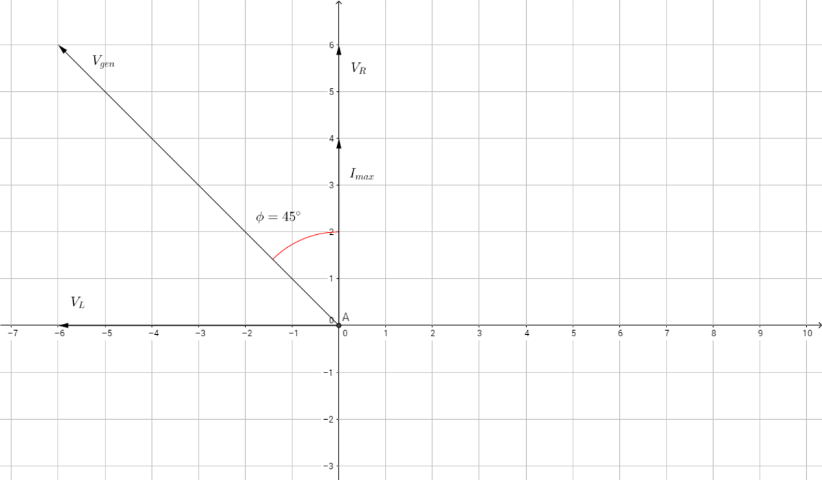
Consider the following phasor diagram:

The vectors rotate about the origin counter-clockwise with angular frequency ω and each has magnitudes corresponding to the maximum voltage/current flowing through the load, with V g e n being the maximum generator voltage and I m a x being the maximum current flowing through the resistor.
The instantaneous magnitudes across each of these elements is given by its corresponding vector's projection on the y-axis, with the sign showing the direction. Note that for an AC circuit 2 M r m s = M m a x , where M is the magnitude of the voltage/current across a circuit element.
The impedance of the circuit Z = R 2 + X L 2 , where X L = ω L , gives us I m a x , since V g e n = Z I m a x
We can also see that ϕ = tan − 1 ( R X L ) = 4 5 ∘ , so we can conclude that in our first scenario ω L = X L = R . It follows that V r m s = X L 2 + X L 2 I r m s , and so X L = R = 1 Ω .
In the second scenario, the frequency, and as a result the angular frequency, is doubled, so X L is doubled as well. Based on the new conditions, X L = 2 Ω and R = 1 Ω since the resistor never changed. This makes impedance 5 Ω , and so I r m s = 5 1 = . 4 4 7
Nice solution. Rotating vectors serve as a conceptual bridge between time-sinusoids and their complex representations. The funny part is that in actual practice, the rotation aspect is almost completely irrelevant, and is customarily ignored. The only things that usually end up mattering are the RMS magnitudes and the relative phase angles. The quantities can therefore be treated as stationary vectors for practical purposes.
Log in to reply
Yes of course. I just thought that someone trying this out without ever seeing phasors before would wonder why I can just draw these vectors and plug things in rather than solve a bunch of differential equations. Seeing what they represent helped me tremendously in understanding how to do these problems. Thanks!
We know that Z R = c o s θ = c o s 4 5 = 2 1 . So Z = R 2 .
Z V = I , so Z = I V = 2 = R 2 . So R = 1 .
Now we know that on phasor diagram, X l and R are perpendicular to each other and the angle between them is
4 5 degrees, which means X l = R or w L = R = 1 or L = w 1 = ( 2 π f ) 1 = 1 2 0 π 1 .
For next case we have w = 2 π f = 2 4 0 π . So w L = 2 .
I = Z V , Z = R 2 + ( w L ) 2 = 1 + 4 = 5 .
Thus I = 5 1 = 0 . 4 4 7