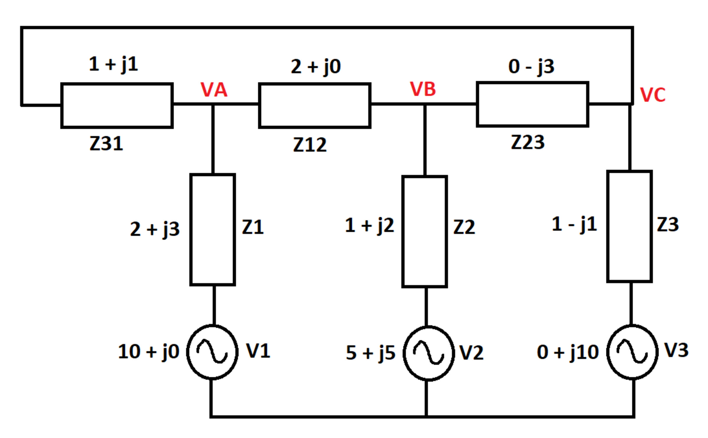
AC Network
In the AC network below, the RMS source voltages are given, and the circuit impedances are given in ohms. What is the total active power (in watts) dissipated in the system impedances?
Hint: It might help to solve for the voltages shown in red

The answer is 30.235.
This section requires Javascript.
You are seeing this because something didn't load right. We suggest you, (a) try
refreshing the page, (b) enabling javascript if it is disabled on your browser and,
finally, (c)
loading the
non-javascript version of this page
. We're sorry about the hassle.
2 solutions
Nice problem! Thanks for the additional notes
Glad you liked it. The active power does indeed correspond to the real part of the V I ∗ expression.
Log in to reply
Yes, the power calculation is the key takeaway for me from this problem. This fills a gap in my conceptual understanding. Thanks again
The circuit equations are:
− V 1 + I 1 Z 1 − I 4 Z 1 2 − I 2 Z 2 + V 2 = 0 − V 2 + I 2 Z 2 + I 5 Z 2 3 − I 3 Z 3 + V 3 = 0 ( I 1 + I 4 ) Z 3 1 − I 5 Z 2 3 + I 4 Z 1 2 = 0 I 2 = I 2 + I 5 I 4 + I 1 + I 5 + I 3 = 0
Solving gives the branch currents. The voltages:
V A = V 1 − I 1 Z 1 V B = V 2 − I 2 Z 2 V C = V 3 − I 3 Z 3
The total power for all impedances is:
P t o t a l = ( V 1 − V A ) I 1 + ( V 2 − V B ) I 2 + ( V 3 − V C ) I 3 + ( V A − V C ) ( I 1 + I 4 ) + ( V B − V A ) I 4 + ( V B − V C ) I 5
This evaluates to:
P t o t a l = − 1 7 1 5 2 − j 1 7 5 1 4
Now, as per my limited understanding of AC circuits, the active power is the real part of the above complex number. However, the answer is the imaginary part 1 7 5 1 4 = 3 0 . 2 3 5 3 . I always thought that the imaginary part is reactive power and not active power. My question is that why is the complex part of the total power the active power and not vice versa?
I will include a few supplementary notes. Assume that we have solved for the currents as @Karan Chatrath has shown. I used the following two ways to calculate the total active power:
Method 1:
P = ∣ I 1 ∣ 2 R e ( Z 1 ) + ∣ I 2 ∣ 2 R e ( Z 2 ) + ∣ I 3 ∣ 2 R e ( Z 3 ) + ∣ I 1 2 ∣ 2 R e ( Z 1 2 ) + ∣ I 2 3 ∣ 2 R e ( Z 2 3 ) + ∣ I 3 1 ∣ 2 R e ( Z 3 1 )
Method 2:
Assume that source currents ( I 1 , I 2 , I 3 ) are leaving the sources:
P = R e ( V 1 I 1 ∗ ) + R e ( V 2 I 2 ∗ ) + R e ( V 3 I 3 ∗ )
In the above equation, the "*" symbol denotes the complex conjugate, and "Re" denotes the real part of a complex number. We could also have used similar V I ∗ expressions for each of the six impedances.