AC with Variable RL (2-19-2021)

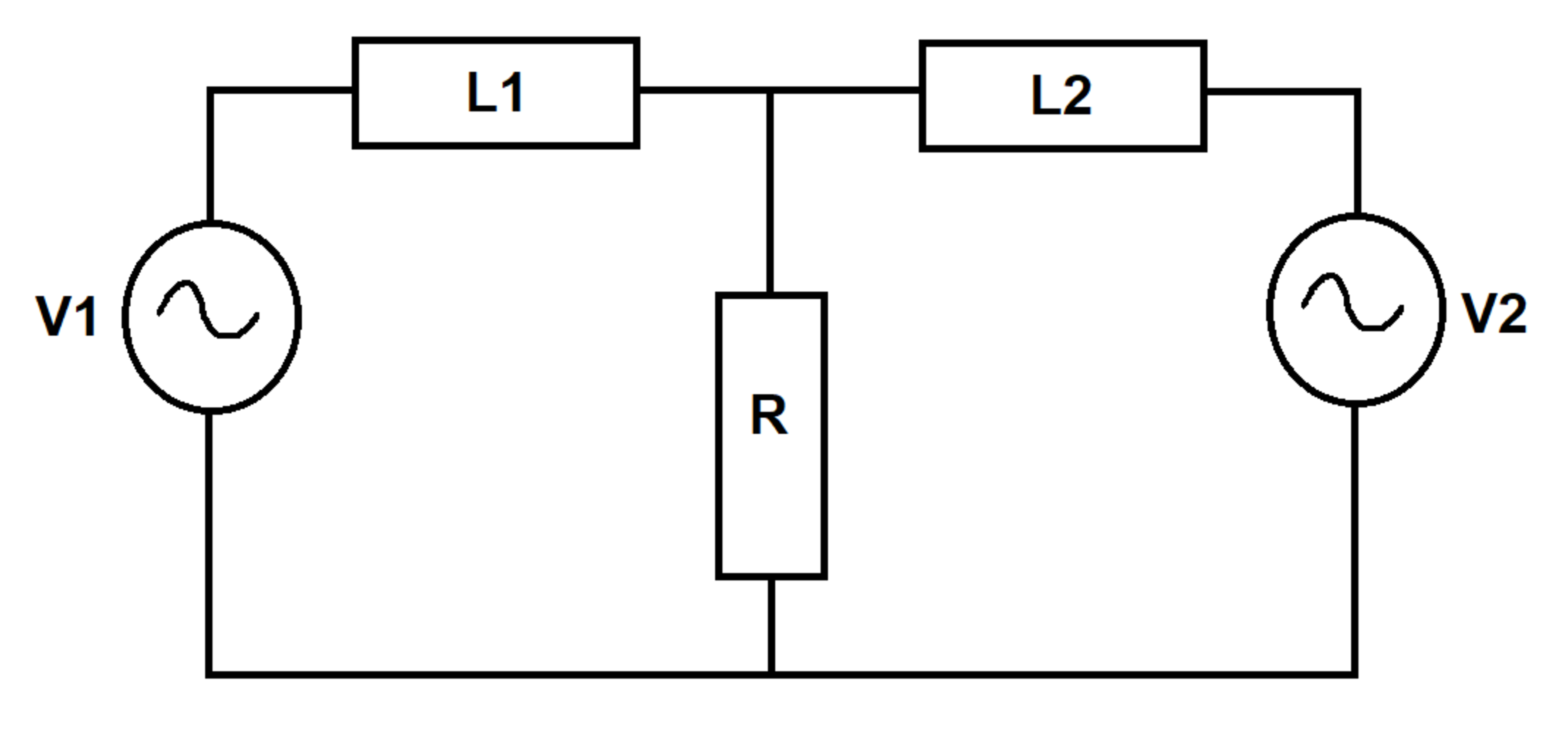
Two AC voltage sources excite an R L RL circuit as shown. The resistor value varies with time. At time t = 0 t = 0 , there is no current flowing in the inductors.

How much energy is dissipated in the resistor between t = 0 t = 0 and t = 0.1 t = 0.1 ?

Bonus: Is energy conserved in this circuit? Broadly speaking, how does the resistor power dissipation depend on the resistance value?

Details and Assumptions:
1) ω = 120 π \omega = 120 \pi (source angular frequency)
2) ω R = 20 π \omega_R = 20 \pi (angular frequency of resistor variation)
3) V 1 ( t ) = 15 sin ( ω t + π / 6 ) V_1(t) = 15 \sin (\omega t + \pi/6)
4) V 2 ( t ) = 10 sin ( ω t ) V_2(t) = 10 \sin (\omega t )
5) L 1 = 5 / ω L_1 = 5 / \omega
6) L 2 = 3 / ω L_2 = 3 / \omega
7) R ( t ) = 1 + sin ( ω R t ) R(t) = 1 + \sin(\omega_R t)


The answer is 1.2147.

This section requires Javascript.
You are seeing this because something didn't load right. We suggest you, (a) try refreshing the page, (b) enabling javascript if it is disabled on your browser and, finally, (c) loading the non-javascript version of this page . We're sorry about the hassle.
2 solutions

Karan Chatrath
Feb 20, 2021

Set source current due to V 1 V_1 be I 1 I_1 and that due to V 2 V_2 be I 2 I_2 . Then:

L 1 I ˙ 1 + R ( I 1 + I 2 ) = V 1 ( 1 ) L_1 \dot{I}_1 + R(I_1+I_2) = V_1 \ \dots \ (1) L 2 I ˙ 2 + R ( I 1 + I 2 ) = V 2 ( 2 ) L_2 \dot{I}_2 + R(I_1+I_2) = V_2 \ \dots \ (2) I 1 ( 0 ) = I 2 ( 0 ) = 0 I_1(0)=I_2(0) = 0

We are asked to compute:

H = 0 0.1 R ( I 1 + I 2 ) 2 d t H = \int_{0}^{0.1} R(I_1 + I_2)^2 \ dt

This problem has been handled numerically, details of which are shown in the code below.

As for energy analysis, multiply (1) by I 1 d t I_1 \ dt and (2) by I 2 d t I_2 \ dt and add:

V 1 I 1 d t + V 2 I 2 d t = L 1 I 1 d I 1 + L 2 I 2 d I 2 + R ( I 1 + I 2 ) 2 d t V_1I_1 \ dt + V_2I_2 \ dt = L_1I_1 \ dI_1 + L_2I_2 \ dI_2 + R(I_1 + I_2)^2 \ dt 0 t V 1 I 1 d t + 0 t V 2 I 2 d t = L 1 I 1 2 2 + L 2 I 2 2 2 + 0 t R ( I 1 + I 2 ) 2 d t \int_{0}^{t}V_1I_1 \ dt + \int_{0}^{t}V_2I_2 \ dt = \frac{L_1I_1^2}{2} + \frac{L_2I_2^2}{2} + \int_{0}^{t} R(I_1 + I_2)^2 \ dt

The above equation clearly tells us that the energy provided by both sources is partly stored in the inductors and partly dissipated in the resistor. Since energy is being dissipated in the resistor, the energy of the circuit is not conserved. If energy was conserved, the energy provided by the source would not be dissipated in any way by the circuit.

As for power dependence on resistance:

P = R ( I 1 + I 2 ) 2 = ( I 1 + I 2 ) 2 + sin ( ω R t ) ( I 1 + I 2 ) 2 P = R(I_1 + I_2)^2 = (I_1 + I_2)^2 + \sin(\omega_R t) (I_1 + I_2)^2

Naively speaking, I would say the power is a linear combination of a component with constant resistance and that with variable resistance. This is obviously not true, because I 1 I_1 and I 2 I_2 both depend on the resistance as can be seen from the governing equations. So essentially, the dependence of power dissipation on the resistance is nonlinear. It is a relation that I do not fully understand at this stage.

 1
 2
 3
 4
 5
 6
 7
 8
 9
10
11
12
13
14
15
16
17
18
19
20
21
22
23
24
25
26
27
28
29
30
31
32
33
34
35
36
37
38
39
40
41
42
43
clear all
clc

% Parameters of circuit:
w           = 120*pi;
wr          = 20*pi;
L1          = 5/w;
L2          = 3/w;

% Time step and end time definitions:
dt          = 1e-5;
tf          = 0.1;
t           = 0:dt:tf;

% Initial conditions:
I1(1)       = 0;
I2(1)       = 0;

% Heat dissipation in resistance initialisation:
H           = 0;

for k = 1:length(t)-1

  % Definitions of source voltages and time-varying resistance:
  T         = t(k);
  V1        = 15*sin(w*T + pi/6);
  V2        = 10*sin(w*T);
  R         = 1 + sin(wr*T);

  % Governing equations of circuit:
  dI1       = (V1 - R*(I1(k) + I2(k)))/L1;
  dI2       = (V2 - R*(I1(k) + I2(k)))/L2;

  % Explicit Euler numerical integration:
  I1(k+1)   = I1(k) + dt*dI1;
  I2(k+1)   = I2(k) + dt*dI2;

  % Computing heat dissipation integral:
  H         = H + (I1(k+1) + I2(k+1))^2*R*dt;
end

ANSWER = H
% ANSWER = 1.2167

Thanks for the solution. I think the results of my latest problem relate to the behavior seen in this problem

Steven Chase - 3 months, 3 weeks ago
Gediminas Sadzius
Feb 20, 2021

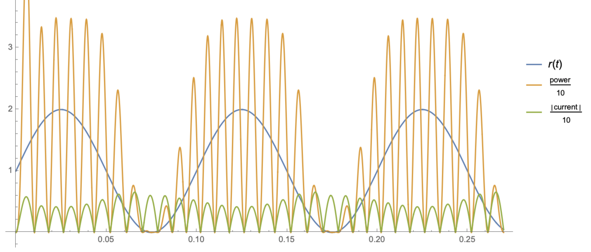
Below is a plot of power dissipated at the resistor, the resistor value and the current. The power lost at the resistor follows both the resistor value and the current - the higher the resistor value the more power is dissipated, as long as there is current flowing through the resistor. The resistor value is set externally. There must be some power input into the system to drive the current, since energy is given away at the resistor.

0 pending reports

×

Problem Loading...

Note Loading...

Set Loading...