Alternate-Universe Inductor
An inductor operates according to the following differential equation (where V and I are time-domain quantities):
V L = L I ˙
Suppose there was an alternate universe in which the voltage across the inductor was related to the second time derivative of the current, instead of the first.
V L = L I ¨
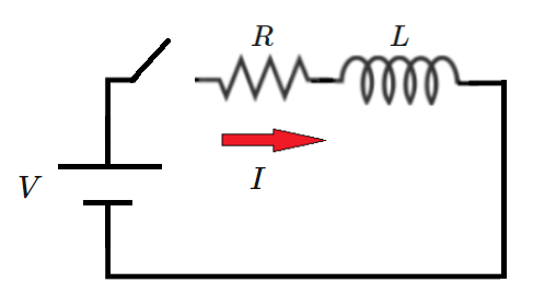
Consider a circuit containing a DC voltage source, a switch, a resistor, and an alternate-universe inductor. For this circuit, the governing differential equation is:
V = R I + L I ¨
Suppose the switch is initially open, and that right after the switch closes, the current has the following properties:
I ( 0 ) = 0 I ˙ ( 0 ) = 0 I ¨ ( 0 ) = L V
The current in the circuit has sinusoidal and non-sinusoidal components. Define the following quantities:
A = peak current value B = average current value (over integer number of signal periods) C = frequency of sinusoidal component (in Hz)
If V = 1 0 volts , R = 2 Ω , and L = 0 . 0 0 1 H , what is A + B + C ?
The answer is 22.118.
This section requires Javascript.
You are seeing this because something didn't load right. We suggest you, (a) try
refreshing the page, (b) enabling javascript if it is disabled on your browser and,
finally, (c)
loading the
non-javascript version of this page
. We're sorry about the hassle.
3 solutions
Interesting problem. Here is a thought. The governing equation for a regular RL circuit is:
V = I R + L I ˙
Multiplying both sides by I and re-arrangement gives:
V I d t = I 2 R d t + L I d I
Integrating the above expression gives us:
∫ 0 ∞ V I d t = ∫ 0 ∞ I 2 R d t + ∫ 0 I s t e a d y S t a t e L I d I
From this equation above, we can draw a well known conclusion that the energy released by the source is partly stored in the inductor and is partly lost as heat due to resistance.
Let us apply this same logic to the alternate universe inductor. The expression for energy stored in the inductor is of a very different nature. Infact, the energy levels in the inductor may be varying with time (this is speculation as I haven't worked out the expression yet).
What are your views on this? An interesting follow up problem could be framed on these lines if this thought is on a right track. I realise that speculating about this is probably meaningless as this is not a representation of reality. But I find it interesting..
This is a good line of inquiry. Let's calculate and compare the following things, given some transient:
1)
Integral of power out of source (straightforward and standard)
2)
Integral of power dissipated in resistor as heat (straightforward and standard)
3)
Integral of power stored in inductor. This would be an integral of instantaneous voltage times current (like the calc for (1))
4)
We know that (1) minus (2) "should" equal (3), if everything hangs together
With a time-domain simulation, we can also verify that these relationships hold on a sample-by-sample basis
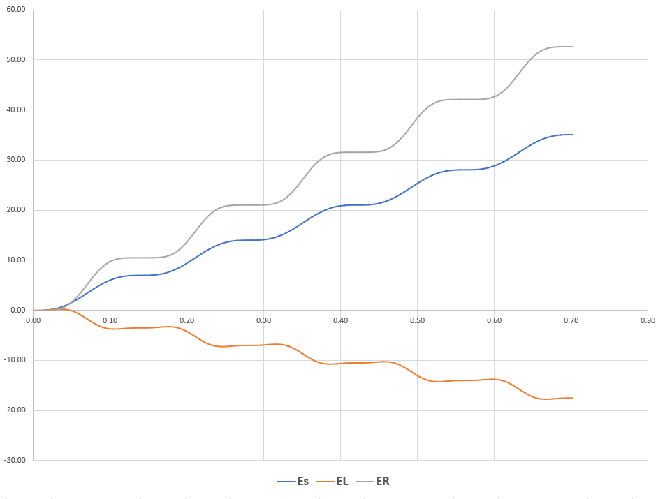
The energy picture seems to hold together. All the checks pass. The third item in my print statement is always basically zero. However, there are a few more very interesting points as well.
1) I am using a load convention for the inductor energy E L . So a positive value for E L indicates net energy consumption. The plot of E L over time shows that the inductor consumes energy for a short time, but then consistently supplies energy to the circuit from then on. The inductor is therefore an "active" element, which would require an internal energy source (like a battery) to sustain.
2) There is no nice proportionality between E L and the square of the current.
3) I am using a source convention for the battery energy E s , and a load convention for the resistor energy E R . These are both generally positive as expected.
1 2 3 4 5 6 7 8 9 10 11 12 13 14 15 16 17 18 19 20 21 22 23 24 25 26 27 28 29 30 31 32 33 34 35 36 37 38 39 40 41 42 43 44 |
|
That is a very detailed analysis. The idea of the inductor being an active element is an interesting deduction. Thank you for the insights.
This can be solved via a Laplace Transform:
I ′ ′ ( t ) + L R ⋅ I ( t ) = L V ⇒ [ s 2 I ( s ) − s I ( 0 ) − I ′ ( 0 ) ] + L R ⋅ I ( s ) = L V ⋅ s 1
and after substituting our values for resistance, inductance, and voltage:
( s 2 + 2 0 0 0 ) I ( s ) = s 1 0 0 0 0 ⇒ I ( s ) = s ( s 2 + 2 0 0 0 ) 1 0 0 0 0 = s 5 − s 2 + 2 0 0 0 5 s ;
and taking the inverse Laplace Transform yields:
I ( t ) = 5 − 5 c o s ( 2 0 0 0 t )
which the following info can be gleaned:
I M I N = 0 , I M A X = 1 0 , I A V G = 2 I M I N + I M A X = 5 and 2 π f = 2 0 0 0 ⇒ f = 2 π 2 0 0 0 = 7 . 1 1 7
and the final answer computes to: I M A X + I A V G + f = 1 0 + 5 + 7 . 1 1 7 = 2 2 . 1 1 7 .
Thanks. Glad to see a solve on this finally
Log in to reply
No prob, Steve......nice little LR circuit problem to kick my Sunday morning off :)
The homogeneous equation is:
I ¨ = − L R I
Combining the homogeneous solution with the particular solution gives the following general form (note that A , B , C are defined differently here than in the original problem statement):
I = A c o s ( L R t ) + B s i n ( L R t ) + C
Applying initial conditions gives:
0 = A + C 0 = B L R ⟹ B = 0 − A L R = L V
Solving for the constants:
A = − R V B = 0 C = R V
The expression for the current is:
I = − R V c o s ( L R t ) + R V
Values of the parameters asked for in the problem:
peak current value = 2 R V = 1 0 average current value = R V = 5 sinusoidal component frequency = 2 π 1 L R = 7 . 1 1 8 sum of all three quantities = 2 2 . 1 1 8