Alternating Current Series #3
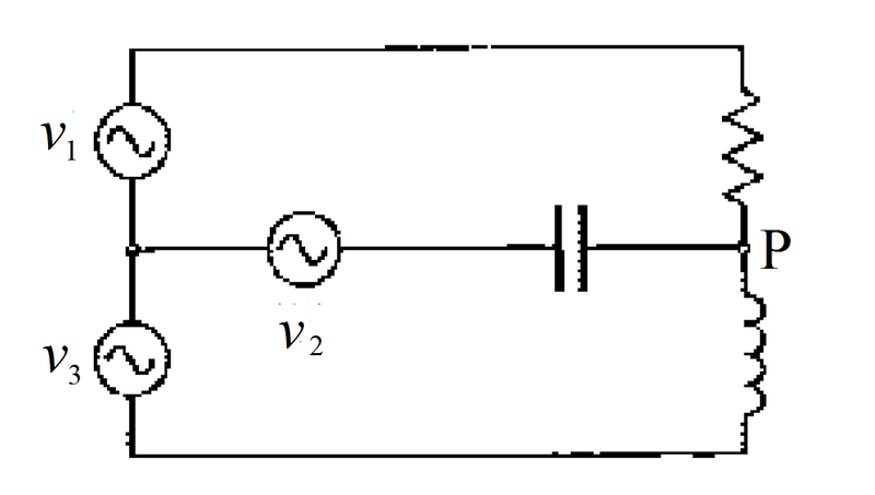
The circuit shown above consists of a resistance, a capacitor, an inductor and three alternating voltage sources:
⎩ ⎪ ⎨ ⎪ ⎧ v 1 = V sin ( ω t ) v 2 = V sin ( ω t + 1 2 0 ° ) v 3 = V sin ( ω t + 2 4 0 ° )
The absolute magnitudes (moduli) of impedance of the resistance, capacitor and inductor are the same. Find the voltage of the junction P , which is of the form v P = α V sin ( ω t + β ° ) . Type your answer as α + β .
The problem is taken from my Physics Book.
The answer is 180.732.
This section requires Javascript.
You are seeing this because something didn't load right. We suggest you, (a) try
refreshing the page, (b) enabling javascript if it is disabled on your browser and,
finally, (c)
loading the
non-javascript version of this page
. We're sorry about the hassle.
2 solutions
@Chew-Seong Cheong
Upvoted. Very nice thanks for solution.
It is good to see you solve Electricity and Magnetism problems also.
Log in to reply
You are welcome. I was trained an electrical engineer.
The key here is to represent the quantities as complex numbers. The voltages are (we can just consider the magnitude to be one):
V 1 = e j 0 ∘ V 2 = e j 1 2 0 ∘ V 3 = e j 2 4 0 ∘
The impedances are (take there magnitudes to be unity):
Z R = 1 + j 0 Z C = 0 − j 1 Z L = 0 + j 1
The nodal equation at P is:
R V P − V 1 + Z C V P − V 2 + Z L V P − V 3 = 0 V P ( R 1 + Z C 1 + Z L 1 ) = R V 1 + Z C V 2 + Z L V 3
Solving for V P results in:
V P = ( 3 − 1 ) e j 1 8 0 ∘
Solution code is attached:
1 2 3 4 5 6 7 8 9 10 11 12 13 14 15 16 17 18 19 20 21 22 23 24 25 26 27 28 29 30 31 32 33 34 |
|
@Steven Chase
Thanks
How can we take magnitude of impedance to be unity?
Log in to reply
Or you can pick any number you want. As long as they have the same magnitude, the result will be the same
Log in to reply
@Steven Chase
Thanks.
By the way, your English skills and vocabulary is excellent.
@Steven Chase
Umm. How did you solve that equation at the last 2nd step of your anayltical solution?
I am facing little bit difficulty?
Log in to reply
These substitutions should help:
j = e j π / 2 − j = e − j π / 2
@Steven Chase
I was not expecting a reply today.
Any way why did you consider magnitudes of. Capacitor and inductor -j and +j
Log in to reply
Indeed, I am going to bed now. Those conventions require a bit of explanation, so I will post a note on the subject tomorrow.
@Steven Chase
Those conventions require a bit of explanation, so I will post a note on the subject tomorrow.
Can you explain now?
Using phasor notation for convenience, then v 1 = V ∠ 0 ∘ , v 2 = V ∠ 1 2 0 ∘ , and v 3 = V ∠ 2 4 0 ∘ . Using the junction O connected to the three voltage sources as reference and considering the sum of current out of node O as zero, and let the magnitude of the impedances be R , then we have:
R v P − v 1 + − j R v P − v 2 + j R v P − v 3 R V p ∠ θ − V ∠ 0 ∘ + − j R V p ∠ θ − V ∠ 1 2 0 ∘ + j R V p ∠ θ − V ∠ 2 4 0 ∘ R V p ∠ θ − V ∠ 0 ∘ + R ∠ 9 0 ∘ V ∠ 1 2 0 ∘ − V ∠ 2 4 0 ∘ V p ∠ θ − V ∠ 0 ∘ + V ∠ 3 0 ∘ − V ∠ 1 5 0 ∘ = 0 = 0 = 0 = 0 Let v P = V p ∠ θ
⟹ V p ∠ θ = V ∠ 0 ∘ − V ∠ 3 0 ∘ + V ∠ 1 5 0 ∘ = V ( 1 − 2 3 − 2 j − 2 3 + 2 j ) = ( 1 − 3 ) V = ( 3 − 1 ) V ∠ 1 8 0 ∘
Therefore α + β = 3 − 1 + 1 8 0 ≈ 1 8 0 . 7 3 2 .