Before Lunar New Year 2016 ends...
One common example of Chinese New Year symbolism is the red diamond-shaped 福 characters ("fortune"), which are displayed on the entrances of Chinese homes. This sign is usually seen hanging upside down, since the Chinese word 倒 ("upside down"), sounds like the Chinese word 到 ("arrive"). Therefore, it symbolizes the arrival of luck, happiness, and prosperity.
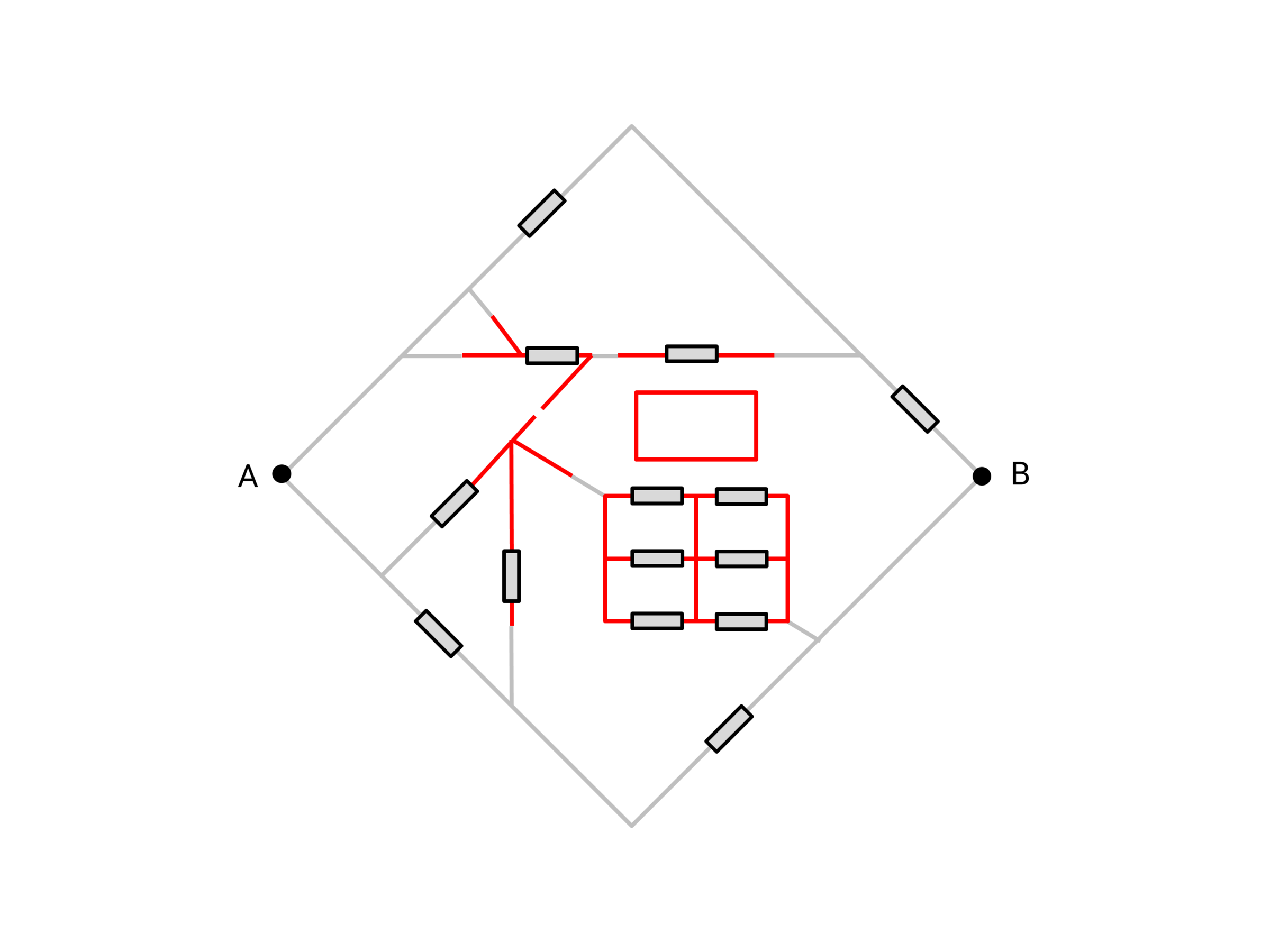
In the above circuit shaped in the Chinese character 福, the 14 tiny grey rectangles are all resistors with identical resistance 1 ohm. The effective resistance across can be expressed in simplest form as where and are coprime. Find .
Note : The isolated red smaller rectangle in the diagram is not part of the circuit. Additionally, as you may have noticed, the break in the circuit is intended. There is no difference between the red and grey wires of the circuit.
The answer is 257.
This section requires Javascript.
You are seeing this because something didn't load right. We suggest you, (a) try
refreshing the page, (b) enabling javascript if it is disabled on your browser and,
finally, (c)
loading the
non-javascript version of this page
. We're sorry about the hassle.
Let us analyse this circuit piece by piece.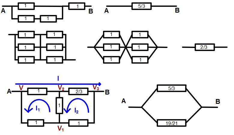 Due to the break in the circuit in the middle of the diagram, there are two separate circuits running from
A
to
B
. The top one consists of
2
Ω
and
1
Ω
in parallel, followed by
1
Ω
in series, for an effective resistance of
(
1
1
+
2
1
)
−
1
+
1
=
3
5
Ω
. See the first row in the diagram above.
Due to the break in the circuit in the middle of the diagram, there are two separate circuits running from
A
to
B
. The top one consists of
2
Ω
and
1
Ω
in parallel, followed by
1
Ω
in series, for an effective resistance of
(
1
1
+
2
1
)
−
1
+
1
=
3
5
Ω
. See the first row in the diagram above.
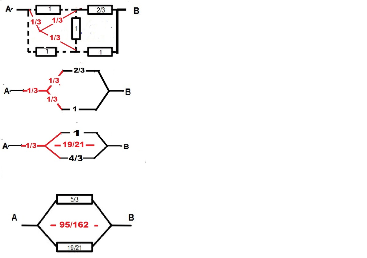
The grouping of six 1 Ω resistors is equivalent, after some vertex collapse, to a series of two triples of 1 Ω resistors in parallel, and hence has effective resistance 2 ( 1 1 + 1 1 + 1 1 ) − 1 = 3 2 Ω . See the second row in the diagram.
The bottom circuit from A to B can thus be represented by the circuit in the bottom-left of the diagram. Suppose that there is a current I passing through this circuit, and that there are circulant currents I 1 and I 2 in the two loops as indicated. Let the voltages at the four key vertices be V , V 1 , V 2 and V 3 as indicated. Then the equations V − V 1 V 1 − V 2 V 2 − V 3 = = = I 1 I 1 − I 2 3 2 ( I − I 2 ) V − V 2 V 1 − V 3 = = I − I 1 I 2 describe the potential losses across each component of the circuit. Solving these simultaneous equations gives I 1 V 1 = = 2 1 1 0 I V − 2 1 1 0 I I 2 V 2 = = 7 3 I V − 2 1 1 1 I V 3 = V − 2 1 1 9 I Thus the effective resistance of the lower circuit is I V − V 3 = 2 1 1 9 Ω .
Thus the whole circuit is equivalent to resistors of 3 5 Ω and 2 1 1 9 Ω in parallel, for an overall effective resistance of ( 5 3 + 1 9 2 1 ) − 1 = 1 6 2 9 5 Ω . This makes the answer 9 5 + 1 6 2 = 2 5 7 .