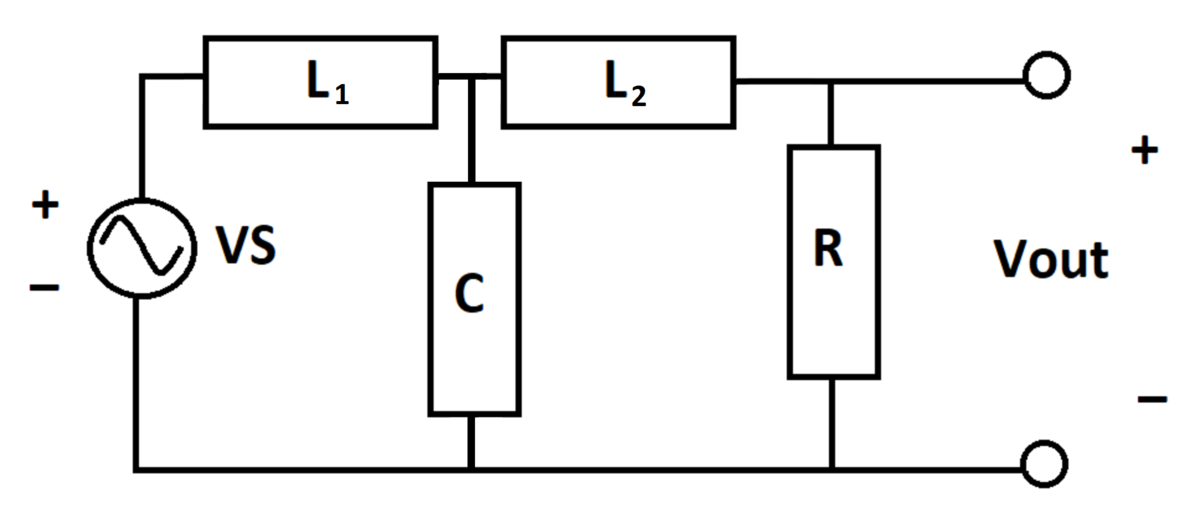
Butterworth Filter with "Square Wave" Input
An Butterworth filter takes a sinusoidal voltage input and produces an output voltage .
is as follows:
Assuming that the filter is in periodic steady-state operation, what is the peak value of ?
Bonus: Plot both the input and output signals and comment on why the output looks the way it does
Details and Assumptions:
1)
This particular filter is described on a
Wikipedia page
2)
3)
4)
5)
The answer is 0.72.
This section requires Javascript.
You are seeing this because something didn't load right. We suggest you, (a) try
refreshing the page, (b) enabling javascript if it is disabled on your browser and,
finally, (c)
loading the
non-javascript version of this page
. We're sorry about the hassle.
As per the Wikipedia article, the transfer function relating the input and output voltage for this circuit is H ( s ) = s 3 + 2 s 2 + 2 s + 1 1 Since this circuit is driven by a sinusoidal source we may set s = j ω , and the output should be a sum of sinusoids with shifted phase and attenuated magnitude. For this case we may write the magnitude response for the circuit as ∣ H ( j ω ) ∣ = 1 + ω 6 1 Next we make use of the superposition principle since the circuit is composed of RLC components, this allows us to say that the output is the sum of the response to each individual sinusoid. Since we are only concerned with magnitudes we may write V o , max = 1 + 1 6 1 + 3 1 + 3 6 1 + 5 1 + 5 6 1 ≈ 0 . 7 2 1 V I did not plot the functions, but one should expect the contribution from the ω = 5 sinusoid to be negligible to the output due the circuit strongly attenuating this frequency, the same likely occurs for the ω = 3 signal. Therefore the output signal is predominantly of frequency ω = 1 and it's magnitude should only slightly deviate from 2 1 .