Capacity of Capacitor
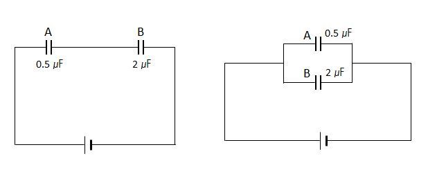 The above two diagrams show capacitors A and B, with their respective capacities
F and
F, connected to an electric circuit in two different ways. The one on the left is a series connection, while the one on the right is a parallel connection. What are the combined capacitance in the above left(
) and right(
) diagrams, respectively?
The above two diagrams show capacitors A and B, with their respective capacities
F and
F, connected to an electric circuit in two different ways. The one on the left is a series connection, while the one on the right is a parallel connection. What are the combined capacitance in the above left(
) and right(
) diagrams, respectively?
This section requires Javascript.
You are seeing this because something didn't load right. We suggest you, (a) try
refreshing the page, (b) enabling javascript if it is disabled on your browser and,
finally, (c)
loading the
non-javascript version of this page
. We're sorry about the hassle.
When capacitors are in series 1/Ceq = (1/C1) + (1/C2) + (1/C3).............. where C1 , C2 , C3 ..... are capacitors in series and Ceq is equivalent capacior. For this case 1/Ceq = 1/0.5 + 1/2 => Ceq = 2*0.5/2.5 = 0.4 uF
When Capaciors are in parallel Ceq = C1 + C2 + C3 ......... C1, C2 , C3 .... are capacitors in parallel IN this case Ceq = 2 + 0.5 = 2.5 uF