Complex current
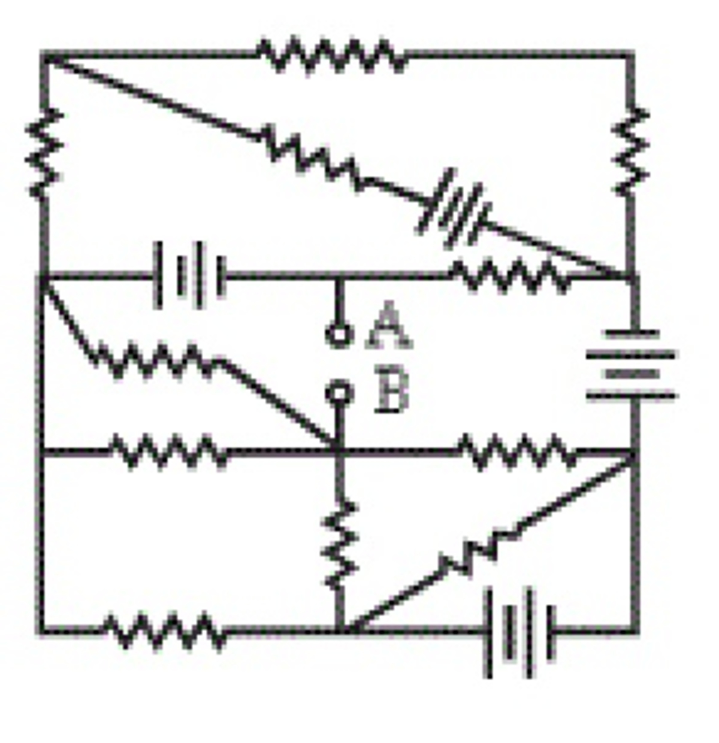
The network shown in the figure above consists of four identical batteries and 11 unknown resistors. When an ideal ammeter is connected between the terminals A and B, its reading is 2 A and when a resistance of is connected in series with the ammeter its reading becomes . Now the ammeter and the resistance are disconnected and an ideal voltmeter is connected between the terminals A and B. What would the voltmeter read?
The answer is 4.
This section requires Javascript.
You are seeing this because something didn't load right. We suggest you, (a) try
refreshing the page, (b) enabling javascript if it is disabled on your browser and,
finally, (c)
loading the
non-javascript version of this page
. We're sorry about the hassle.
By Thévenin's theorem , any circuit of voltage sources and resistors with two terminals can be transformed into an equivalent circuit of a voltage source and a resistance (see left figure above). From the equivalent circuits above, we have:
⎩ ⎪ ⎨ ⎪ ⎧ R T h V T h = 2 R T h + 2 V T h = 1 ⟹ V T h = 2 R T h ⟹ V T h = R T h + 2 . . . ( 1 ) . . . ( 2 )
( 1 ) = ( 2 ) : 2 R T h ⟹ R T h ( 1 ) : V T h = R T h + 2 = 2 Ω = 2 R T h = 4 V