Computational Physics (Mechanical System)
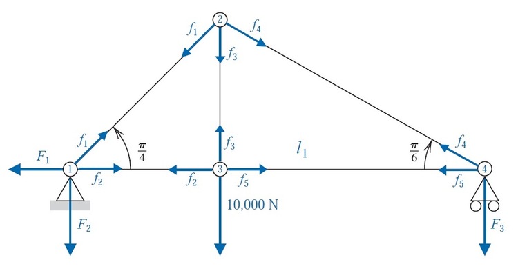
 Trusses are lightweight structures capable of carrying heavy loads. In bridge design, the individual members of the truss are connected with rotatable pin joints that permit forces to be transferred from one member of the truss to another. The accompanying figure shows a truss that is held stationary at the lower left endpoint
, is permitted to move horizontally at the lower right endpoint
, and has pin joints at
,
,
, and
. A load of
is placed at joint
, and the resulting forces on the joints are given by
,
,
,
, and
, as shown. When positive, these forces indicate tension on the truss elements, and when negative, compression. The stationary support member could have both a horizontal force component
and a vertical force component
, but the movable support member has only a vertical force component
.
If the truss is in static equilibrium, then based on Newton's law of motion the forces at each joint must add to the zero. Thus, the sum of the horizontal and vertical components at each joint must be . Calculate the value of where
The answer is 48966.
This section requires Javascript.
You are seeing this because something didn't load right. We suggest you, (a) try
refreshing the page, (b) enabling javascript if it is disabled on your browser and,
finally, (c)
loading the
non-javascript version of this page
. We're sorry about the hassle.
There are eight scalar unknowns and four joints, each with two equilibrium conditions (x and y). We therefore have eight linear equations to solve for eight unknowns.
1 X : − F 1 + f 2 + f 1 c o s 4 π = 0 1 Y : f 1 s i n 4 π − F 2 = 0 2 X : − f 1 s i n 4 π + f 4 s i n 3 π = 0 2 Y : − f 1 c o s 4 π − f 4 c o s 3 π − f 3 = 0 3 X : − f 2 + f 5 = 0 3 Y : f 3 − 1 0 0 0 0 = 0 4 X : − f 5 − f 4 c o s 6 π = 0 4 Y : f 4 s i n 6 π − F 3 = 0
Solving and summing the force magnitudes gives 48966 (when taking the ceiling).