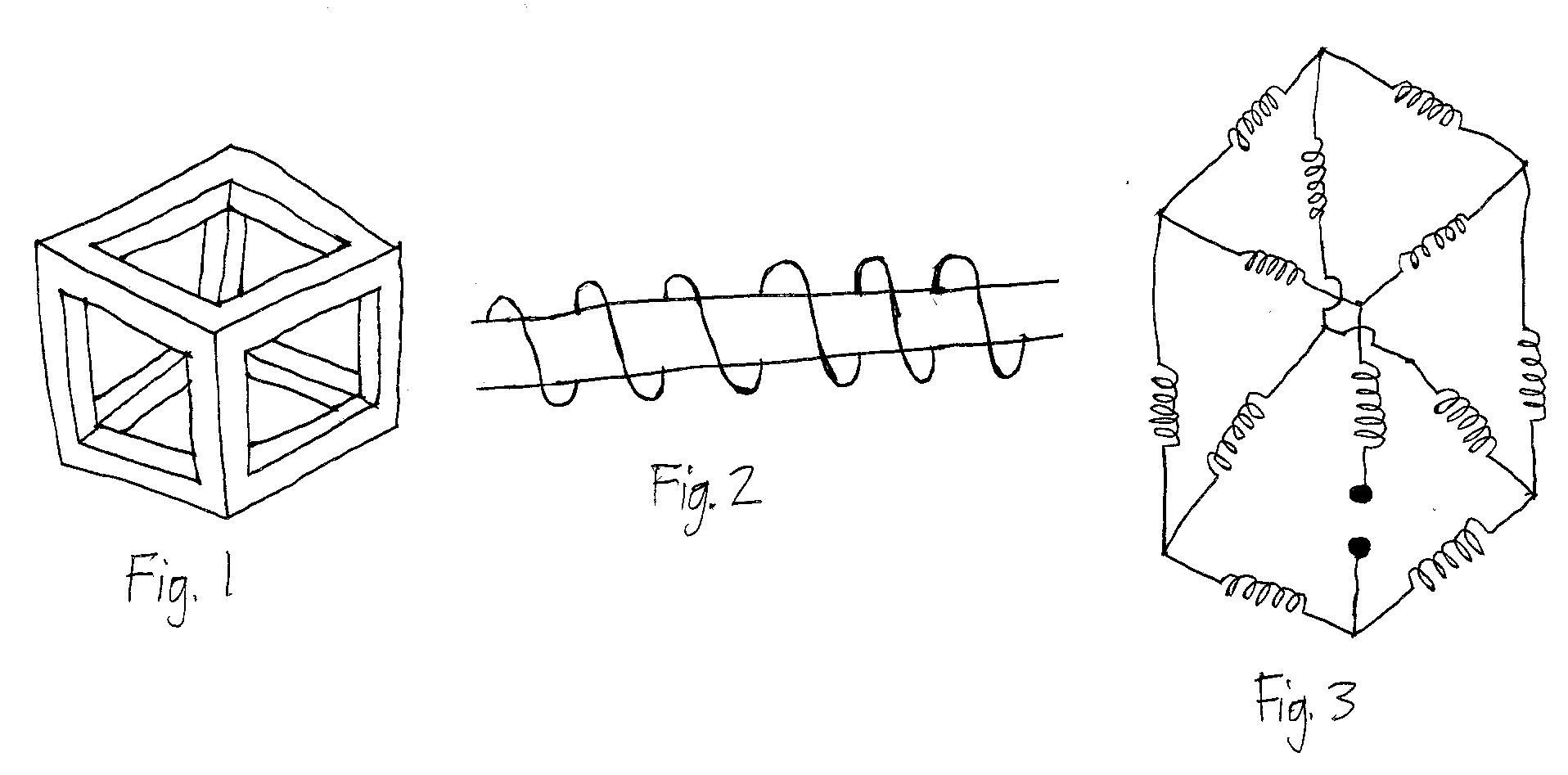
Cube Of Magnetically Coupled Coils

Figure 1 shows a cubic frame with side length . The frame is made of a material with magnetic permeability . Each arm of the frame has cross sectional area . In each arm, the magnetic field is uniform and also parallel to the arm. Also, , and , where is the magnetic permeability of free space.
An turn coil ( ) is wound around each arm of the frame. Figure 2 shows, for all arms of the frame, how a coil is wound around an arm. Also in Figure 2, pay particular attention to the direction of the magnetic field produced by the current in the coil.
Figure 3 shows how the coils are electrically connected. The shaded dots indicate the terminals of the system.
The inductance of the system as seen across its terminals is
where and are positive coprime integers. Determine .
The answer is 17.
This section requires Javascript.
You are seeing this because something didn't load right. We suggest you, (a) try
refreshing the page, (b) enabling javascript if it is disabled on your browser and,
finally, (c)
loading the
non-javascript version of this page
. We're sorry about the hassle.
The vertices of the cube are labeled according to this figure:
Symmetry
The system exhibits a symmetry across the plane 1 2 0 7 . Also, the upper half and the lower half of the cube are symmetric.
Gauss Law for Magnetic Fields
Knowing that the total magnetic flux entering each vertex is zero, and combining that with the symmetries of the problem:
μ A H 2 5 = μ A H 2 3 = μ A H 6 1 = μ A H 4 1 = 2 μ A H 1 2
μ A H 5 0 = μ A H 3 0 = μ A H 7 6 = μ A H 7 4 = 2 μ A H 0 7
μ A H 5 6 = μ A H 3 4 = 2 μ A ( H x − H y )
where H x = H 1 2 and H y = H 0 7 .
Kirchoff's Current Law
Analogously, we can write the following equations for the currents:
I 2 5 = I 2 3 = I 6 1 = I 4 1 = 2 I 1 2
I 5 0 = I 3 0 = I 7 6 = I 7 4 = 2 I 0 7
I 5 6 = I 3 4 = 2 I x − I y
where I x = I 1 2 and I y = I 0 7 .
Figure 2 and Ampere's Law
Suppose that the left end of the arm in Figure 2 is labeled as J and the right end K . Suppose that as part of our Amperean loop, we traverse this arm from the left end to the right end. Thus, in our Ampere's Law equation, we add + s H J K to the left side of the equation, and + N I J K to the right side of the equation.
Ampere's Law
We apply Ampere's Law to loops 1 2 5 6 and 7 0 5 6 :
s ( 2 H x + H x + 2 H x − H y + 2 H x ) = N ( 2 I x + I x + 2 I x − I y + 2 I x )
s ( 2 H y + H y + 2 H y − H x + 2 H y ) = N ( 2 I y + I y + 2 I y − I x + 2 I y )
Solving for H x and H y in these two equations yields H x = s N I x and H y = s N I y .
Self Inductances and Mutual Inductances
Notice the parallelism between the equations derived from Gauss Law and the equations derived from KCL. Using the equations derived from Ampere's Law, it can be easily shown that, for all arms of the cubic frame, the magnetic field H of an arm and its corresponding coil current I are related by H = s N I . Notice that the magnetic field in an arm depends only on its corresponding coil current and does not depend on other coil currents. This means that we can effectively simplify the circuit of Figure 3 with all coils having the same effective self inductance and without worrying about mutual inductance.
Magnetic Flux Linkage and Equivalent Inductance
The magnetic flux linkage through a coil is N A μ s N I . Thus, the effective self inductance of each coil is s u N 2 A . Simplifying the circuit of Figure 3:
5 1 2 s μ N 2 A