Cube Resistance Network (Part 2)
Form a resistance network with the following steps:
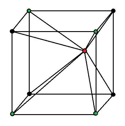
1)
Start with a wire frame cube consisting of
line segments, each with resistance
2)
From a point inside the cube, draw
line segments to the vertices of the cube, each with resistance
3)
Connect the interior point (colored red) to the positive terminal of a battery
4)
Connect
of the cube vertices (colored green) to the negative terminal of the same battery (see diagram)
5)
Leave
of the cube vertices (colored black) as simple nodes connecting cube edges (see diagram)
What equivalent resistance does the network present to the battery?
The answer is 0.15135.
This section requires Javascript.
You are seeing this because something didn't load right. We suggest you, (a) try
refreshing the page, (b) enabling javascript if it is disabled on your browser and,
finally, (c)
loading the
non-javascript version of this page
. We're sorry about the hassle.
Firstly consider the outside cube, and the effect of shorting together the four green vertices. The diagram below shows the effect of doing this:
The next series of diagrams adds the red vertex and the additional eight resistors (four of which have combined in parallel to give a single resistance of 4 1 Ω ). Some elementary series-parallel calculations, plus two Y - Δ transformations, give the effective resistance as 1 8 5 2 8 Ω .