Delta Wye Power
Electricity and Magnetism
Level
3
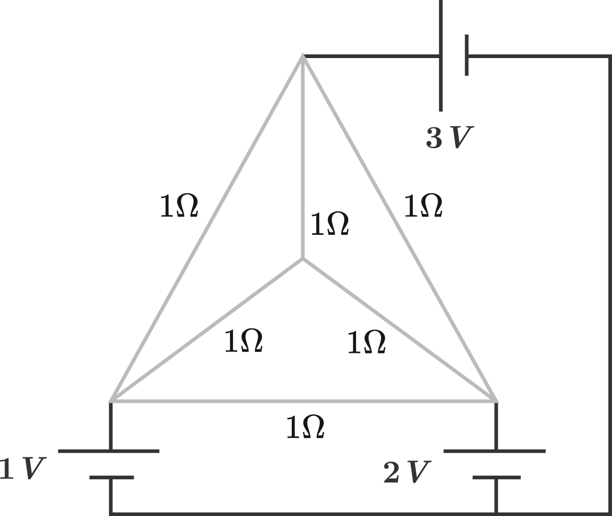
How much power (in watts) is dissipated in the circuit, assuming that the sources are ideal?
The answer is 8.0.
This section requires Javascript.
You are seeing this because something didn't load right. We suggest you, (a) try
refreshing the page, (b) enabling javascript if it is disabled on your browser and,
finally, (c)
loading the
non-javascript version of this page
. We're sorry about the hassle.
Since we want to do this by hand and not use any simulation software, let's make our lives a little bit easier.
We can always choose one reference point whose electric potential is 0 V. However, we must do this smartly. All the voltage sources share the same node (the negative pole if you will). If we choose this node as a reference node, then we know the potentials of the edge nodes of the resistance grid (they are equal to source voltages), and the grid can be reduced to the following: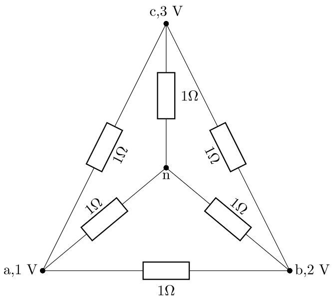
Now, the outer resistors are connected in delta and the inner resistors are connected in wye. We can simplify the circuit further by transforming the wye into delta or delta into wye. I chose to transform the inner wye resistors into delta: R a b = R c n R a n R b n + R a n R c n + R b n R c n R a c = R b n R a n R b n + R a n R c n + R b n R c n R b c = R a n R a n R b n + R a n R c n + R b n R c n
Since all the resistors are equal and 1 Ω , the equivalent delta resistors are 3 Ω each:
If you look carefully, you can see that we basically have a delta connection where the resistors in each branch are connected in parallel. The equivalent resistance of two parallel resistors can be calculated as: R parallel = R 1 + R 2 R 1 × R 2
Finally, the grid reduces to: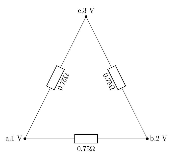
The total power dissipated in this circuit is equal to the sum of powers dissipated on each of the resistors. Since the resistances are known and the voltages accross each of the resistanes are also known (they are equal to potential differences between nodes), we can calculate the power according to: P i j = R i j V i j 2 = R i j ( V i − V j ) 2 P a b = 0 . 7 5 ( 1 − 2 ) 2 = 3 4 W P a c = 0 . 7 5 ( 1 − 3 ) 2 = 3 1 6 W P b c = 0 . 7 5 ( 2 − 3 ) 2 = 3 4 W Finally, the total power dissipated is: P total = P a b + P a c + P b c = 3 4 + 3 1 6 + 3 4 = 8 W Also, check out these quick simulations: The total power dissipated in the circuit is equal to the sum of total powers dissipated on the resistors. This total power also must equal the sum of source powers. Power of the source is equal to: P s r c = V s r c × I s r c
The first image shows the original circuit. The current from the first voltage source is -4 A, the current from second source is 0 A and the current from third source is 4 A. The total power of the circuit is: P total = P s r c 1 + P s r c 2 + P s r c 3 = − 4 × 1 + 0 × 2 + 4 × 3 = 8 W The second figure shows the reduced equivalent circuit with all the resistors equal to 0.75 Ω . You can see that the source currents do not change and the total power of the circuit is the same as in the first circuit.