Flow Rate Through a Large Circular Orifice
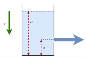
The tank shown alongside is filled with water. The tank has a large circular orifice of diameter d = 2 m at a height of h = 2 m from the bottom of the tank. At a certain instant of time, the height of water in the tank is H = 1 0 m . The goal of this problem is to compute the volumetric flow rate Q ˙ through this orifice at this instant. Assume that the coefficient of discharge through the orifice is unity.
Enter your answer as ⌊ 1 0 0 0 Q ˙ ⌋ .
Note:
- Acceleration due to gravity: g = 1 0 m / s 2 .
- Water is incompressible and the flow through the orifice is steady and laminar.
- Assume that the cross-section area of the orifice is comparable to the cross-section area of the tank.
- The centre of the orifice is at a height h above the tank bottom.
Bonus: Also calculate the result assuming that the cross-section area of the orifice is much less than the cross-section area of the tank and compare the results.
The answer is 39718.
This section requires Javascript.
You are seeing this because something didn't load right. We suggest you, (a) try
refreshing the page, (b) enabling javascript if it is disabled on your browser and,
finally, (c)
loading the
non-javascript version of this page
. We're sorry about the hassle.
1 solution
Thanks for the solution. Back in my bachelor of engineering days, in our fluid mechanics course, we were asked to conduct experiments on various geometries and to compute the average ratio of the measured flow rate and theoretical flow rate (assuming ideal conditions). This ratio is the discharge coefficient. It is a single parameter that accounts for nonlinear fluid behaviour understanding which would otherwise require a more elaborate treatment.
To be rigorous, one would need to solve the Navier Stokes equations for viscid and incompressible flow to correctly model the fluid flow through the orifice. One way of doing this is by using numerical techniques (computational fluid dynamics) to solve for the flow rate and then compare it with the idealised flow rate to compute this lumped parameter. This exercise would also require experimental verification. But indeed, as you mentioned, overdesign based on simple calculations, to provide a safety margin is still the popular method.
Log in to reply
Haha fluid mechanics is in an entire different class of its own...
Since I already wrote this, I'll just leave it here.
In the diagram you have h shown as the center of the orifice ( or it appears that way ).
Thus, If we measure from the top of the orifice with distance x
v ( x ) = 2 g ( 7 + x )
Then, we will have that:
d A = 2 ⋅ 2 r x − x 2 d x
Finally:
Q = ∫ v ⋅ d A = 2 ⋅ 0 m ∫ 2 m 2 g ( 7 + x ) ⋅ 2 r x − x 2 d x = 3 9 . 7 1 8 s m 3
Log in to reply
Strange. Your method is correct, so I evaluated the integral myself. I get the correct answer.
Log in to reply
Your right! I I goofed up something using the calculation software. Thanks for your reply.
Seeing the "floor one thousand" requirement let me know that this was not supposed to be a completely trivial problem, so I used integral calculus combined with Toricelli's Law. Basically, divide the hole into horizontal strips, with each strip having its own infinitesimal area and a flow rate depending on the height relative to the top of the water. And then afterward, I did the most trivial possible calculation and compared. The results are quite similar.
I do wonder about one thing though. If the flow speed is non-uniform, are there frictional losses as a result of relative movement between different fluid layers? Maybe this would result in a "coefficient of discharge" less than one. But then I doubt it would be appropriate to use a single coefficient for the whole system. I suppose in practice they just empirically measure coefficients for different geometries and call it a day. Probably the best thing for an engineer to do is to use a somewhat simplified calculation and then over-build to provide margin.