Follow-up to Max Power Transfer
Start with the circuit from this problem . This problem assumes that you have calculated the capacitance value.
The capacitor and inductor are de-energized at time t = 0 . If V ( t ) is the source voltage and I ( t ) is the current flowing out of the source, determine the following integral:
∫ 0 ∞ ( V ( t ) − I ( t ) ) d t
Note: If you are concerned about mismatched units in the integral, you can imagine that there is a 1 Ω multiplier on the current
The answer is 0.333.
This section requires Javascript.
You are seeing this because something didn't load right. We suggest you, (a) try
refreshing the page, (b) enabling javascript if it is disabled on your browser and,
finally, (c)
loading the
non-javascript version of this page
. We're sorry about the hassle.
3 solutions
Thanks for the solution. By the way, I would be interested in seeing what you get for the problem called "Hard Dynamics 4"
Log in to reply
Ya, I saw that problem but felt lazy to have a go at it. I'll give it a shot in some time soon and share my thoughts.
I obtain an answer of 3.6671 s which is marked as incorrect.

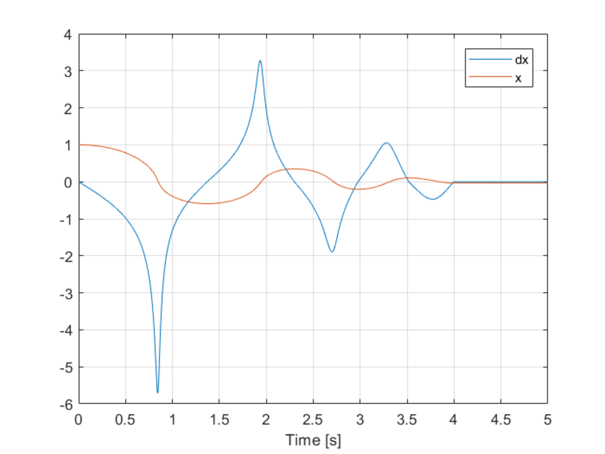
The variation of X coordinate and X component of velocity with time. This to me seems like a reasonable result. This is the 'Hard Dynamics 4' problem result. What are your thoughts?
Log in to reply
Thanks for checking. I also got 3.67. The first stop occurs at t = 1 . 3 7 with x = − 0 . 5 9 . The second stop occurs at t = 2 . 3 0 with x = 0 . 3 5 .
@Karan Chatrath has shown how to derive the result. I got the inspiration for this problem by noting that the complex impedance of the circuit is 1 Ω (purely resistive) at the frequency of interest. This means that in AC steady-state, the source voltage and source current are exactly the same. Only in the beginning transient period are they different. This is why the integral of the difference between the two is finite, even when calculated over an infinite span of time.
By same proces as @Karan Chatrath I acquired V(s) and I(s). I than integrated in the s-domain and used the Final value theorem (Wikipedia) to evaluate. I'm gonna leave out the final algebra: Please yell at me if that's unacceptable or the following is flawed :
∫ 0 t ( v ( t ) − i ( t ) ) d t = L ⇒ s 1 × ( V ( s ) − I ( s ) )
By final value theorem:
t → ∞ lim ∫ 0 t ( v ( t ) − i ( t ) ) d t = s → 0 lim s × s 1 × ( V ( s ) − I ( s ) ) = 1 − R 1 + R 2 1
Inserting the values
∫ 0 ∞ ( v ( t ) − i ( t ) ) d t = 1 − 1 + 0 . 5 1 = 3 1
Brilliant approach!
I believe there is a (formal) flaw in the argument: If you check the prerequisites, you can only use the Final Value Theorem if all poles lie in the open left plane or at s = 0 (though no multiple poles at s = 0 ). The voltage source V ( s ) however contains a complex pole-pair on the imaginary axis, and so does I ( s ) !
Before you can use the Final Value Theorem, you must check whether the poles on the imaginary axis all cancel out when you simplify V ( s ) − I ( s ) - only then can you be sure the result of the Final Limit Theorem is valid. In this problem however, they do cancel and everything works out fine :)
Circuit equations:
1 0 0 sin ( 1 0 0 t ) = I R 1 + L I ˙ + C Q 1 C Q 1 = I 2 R 2 I = I 1 + I 2 I 1 = Q ˙ 1
Laplace on both sides:
s 2 + 1 0 0 0 0 1 0 0 0 0 = I ( s ) R 1 + s L I ( s ) + C Q 1 ( s ) C Q 1 ( s ) = I 2 ( s ) R 2 I ( s ) = I 1 ( s ) + I 2 ( s ) I 1 ( s ) = s Q 1 ( s )
Solving for I ( s ) gives:
I ( S ) = ( s 2 + 1 0 0 0 0 ) ( s 2 + 2 0 0 s + 3 0 0 0 0 ) 2 0 0 0 0 0 0 ( s + 1 0 0 )
Inverse Laplace transform:
I ( t ) = 1 0 0 sin ( 1 0 0 t ) − 5 0 2 e − 1 0 0 t sin ( 1 0 0 2 t )
It is easy to spot, then, that:
V ( t ) − I ( t ) = 5 0 2 e − 1 0 0 t sin ( 1 0 0 2 t )
Therefore, the required integral is:
∫ 0 ∞ 5 0 2 e − 1 0 0 t sin ( 1 0 0 2 t ) d t = 3 1