Generator Spinning Down
A single-phase electric generator supplies power to a rotating shaft via a combustion engine. The shaft has moment of inertia , variable angular position , and angular speed .
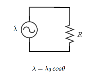
There is an electromagnet attached to the rotating shaft which creates a magnetic flux linkage of the form in the stator coil. The stator coil contains a load resistor, and for simplicity, let us assume that the voltage impressed upon the stator resistance is the time derivative of the flux linkage.
Under normal conditions, the average speed of the generator shaft remains constant because the average mechanical power fed to the shaft matches the average electrical power consumed by the load.
In the above equation, is the instantaneous mechanical power supplied to the shaft by the combustion engine. is the instantaneous electrical power consumed by the stator resistance. is the instantaneous rate of change of the shaft kinetic energy. Note that the above equation neglects friction and other losses.
Suppose the combustion engine shuts off and goes to zero. After the engine shuts off, what is the equation for the angular acceleration of the generator shaft?
This section requires Javascript.
You are seeing this because something didn't load right. We suggest you, (a) try
refreshing the page, (b) enabling javascript if it is disabled on your browser and,
finally, (c)
loading the
non-javascript version of this page
. We're sorry about the hassle.
Time derivative of flux linkage:
λ ˙ = − λ 0 s i n θ θ ˙
Electrical power consumed by stator resistance:
P R = R λ ˙ 2 = R λ 0 2 s i n 2 θ θ ˙ 2
Shaft kinetic energy and its time derivative:
E = 2 1 I θ ˙ 2 E ˙ = I θ ˙ θ ¨
Power balance equation with no input mechanical power:
− P R = E ˙ − R λ 0 2 s i n 2 θ θ ˙ 2 = I θ ˙ θ ¨ θ ¨ = − I R λ 0 2 s i n 2 θ θ ˙