Give and Take
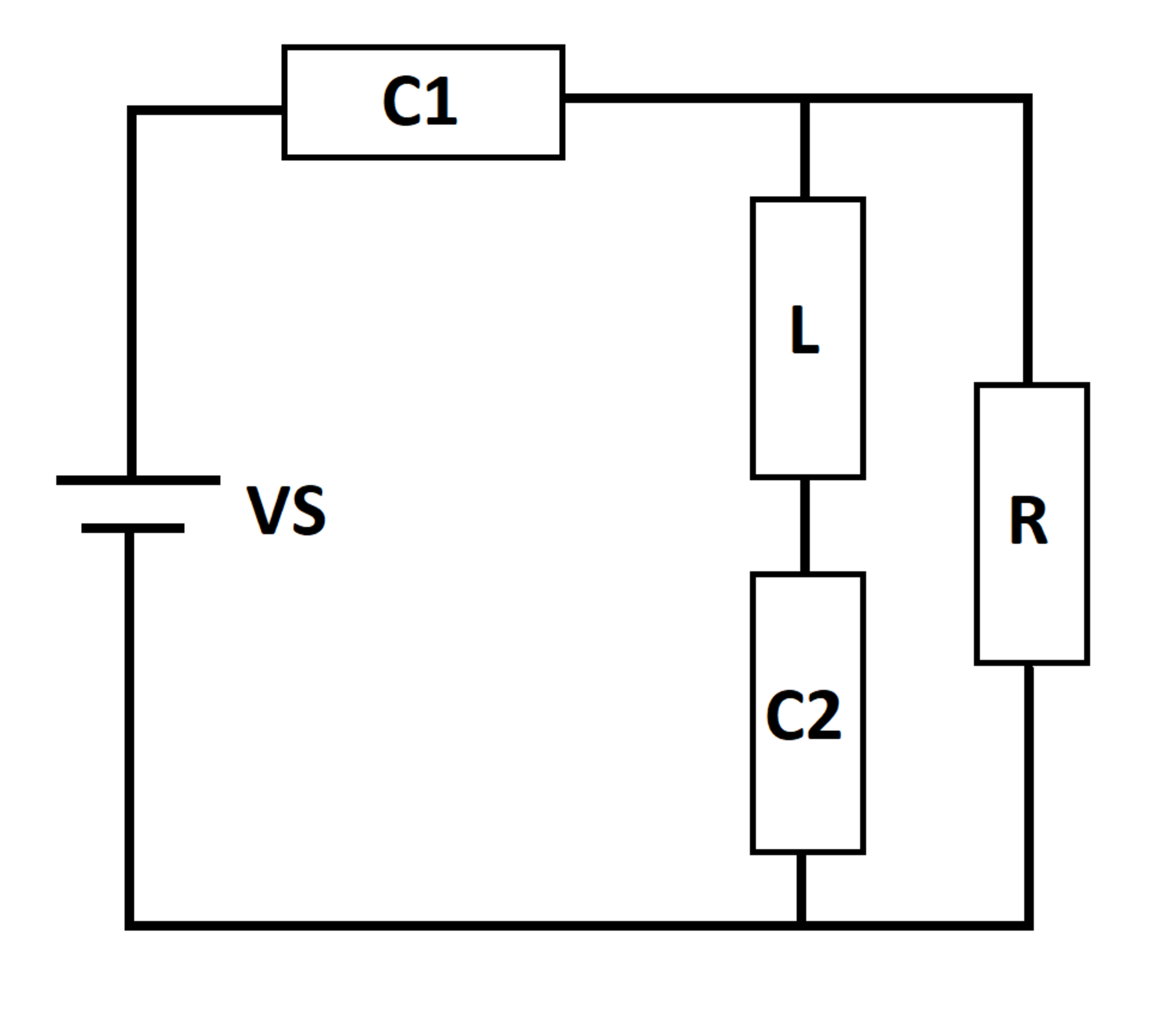
A DC voltage source excites an RLC circuit. At time t = 0 , the inductor and capacitors are de-energized. Let E S ( t ) be the cumulative energy supplied by the source to the rest of the circuit, as of time t .
Let E S ∞ be the value of E S ( t ) as t approaches infinity. Let E S m a x be the largest value of E S ( t ) over all time.
What is E S ∞ E S m a x ?
Details and Assumptions:
1)
V
S
=
1
0
2)
R
=
1
3)
L
=
1
4)
C
1
=
1
5)
C
2
=
1

The answer is 1.105.
This section requires Javascript.
You are seeing this because something didn't load right. We suggest you, (a) try
refreshing the page, (b) enabling javascript if it is disabled on your browser and,
finally, (c)
loading the
non-javascript version of this page
. We're sorry about the hassle.
1 solution
Those plots are very nice, thanks. I hadn't realized the one-half property. One property I observed is that E S ∞ always ends up being the square of the source voltage (with these circuit parameters, at least)
Log in to reply
Interesting observation. If I think about it carefully, it does make sense too.
E S = ∫ 0 ∞ ( V S I ( t ) ) d t
Andthe current expression can be arranged to resemble a structure of Ohm's law, and can be written without loss of generality as:
I ( t ) = R V S f ( R , C 1 , C 2 , L , t )
The function f would comprise of decaying exponentials (multiplied with sinusoids) which would be negligible after a significant amount of time, just leaving the steady-state term. From here, for this given set of parameters, this result should follow. Of course, a closed-form solution would be needed to confirm this line of thought.
The solution method will be brief. I will focus more on the results.
Let the source current be I , current through inductor be I 2 and that through the resistor be I 1 . The charge on capacitor C 1 is denoted as Q and that on capacitor C 2 is Q 2 . Circuit equations are:
V S = L I ˙ 2 + C 1 Q + C 2 Q 2 I 1 R = L I ˙ 2 + C 2 Q 2 I = I 1 + I 2 ; Q ˙ = I ; Q 2 ˙ = I 2
The initial conditions can be computed by recognising that each capacitor has no charge at t = 0 , the current through the inductor is zero at that instant and the current through the resistor is I ( 0 ) = 1 0 A . Numerical integration yields the answer of 1 . 1 0 4 6 . What is really interesting about this problem can be summarised in the plot below: