Invisible Transmission Line

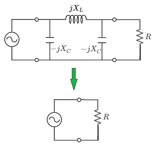
Consider an ideal AC voltage source connected to the input terminals of a transmission line modeled as a pi circuit with two shunt capacitors and a series inductor. Parameters X L and X C represent the absolute magnitudes (in ohms) of the inductive and capacitive reactances, respectively. Note that the impedances consist of the reactances with positive or negative imaginary-unit terms.
Suppose that a resistor is connected to the output terminals of the transmission line. For a particular special value of the resistance, the source draws the same current as it would if the resistor were connected directly to the source terminals. In this special case, the transmission line is effectively "invisible" to the source.
The resistance value which accomplishes this can be expressed as:
R = α + β X C X L X L X C
What is the value of β α ?
The answer is -2.
This section requires Javascript.
You are seeing this because something didn't load right. We suggest you, (a) try
refreshing the page, (b) enabling javascript if it is disabled on your browser and,
finally, (c)
loading the
non-javascript version of this page
. We're sorry about the hassle.
2 solutions

Here is a sketch of the solution. The actual work is fairly tedious, since it has to be kept symbolic the entire way.
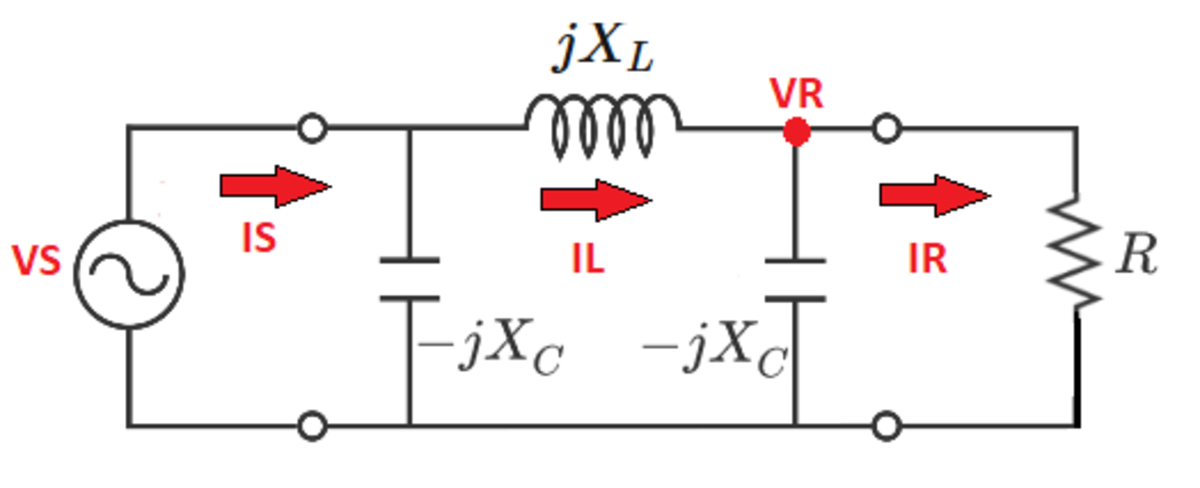
1) We know that for a particular value of the resistance, the source draws current as if that resistance is the only thing connected between its terminals.
I S = R V S
2) Calculate the inductor current:
I L = I S − − j X C V S
3) Calculate the voltage across the resistor:
V R = V S − I L ( j X L )
4) Calculate the current through the resistor:
I R = I L − − j X C V R
5) Determine an alternate expression for the voltage across the resistor:
V R = I R R
6) Equate the two expressions for the voltage across the resistor:
I R R = V S − I L ( j X L )
7) Solving the last expression for the resistance yields:
R = 2 − X C X L X L X C
A numerical parameter sweep of the resistance confirms the legitimacy of this result.
We will calculate the equivalent impedance of the circuit, as seen from the source side. We will make it equal to the load resistance to ensure that the current is the same. We will solve the equation to the load resistance. .
First, we have the load resistor and the capacitor in parallel
Z 1 = R − j X C − j X C R
This is in series with the inductance:
Z 2 = j X L + R − j X C − j X C R
Finally this is parallel to the other capacitor:
Z 3 = Z 2 − j X C − j X C Z 2 = j X L + R − j X C − j X C R − j X C − j X C ( j X L + R − j X C − j X C R )
For the current to be the same this has to be equal to R , Z 3 = R , or
− j X C ( j X L + R − j X C − j X C R ) = R ( j X L + R − j X C − j X C R − j X C )
or
X L X C − R − j X C X C 2 R = j X L R − j X C R − R − j X C j X C R 2
or
X L X C ( R − j X C ) − X C 2 R = ( j X L R − j X C R ) ( R − j X C ) − j X C R 2
or
X L X C R − j X L X C 2 − X C 2 R = j X L R 2 − j X C R 2 + X L X C R − X C 2 R − j X C R 2
There are several terms that cancel each other and we are left with:
− j X L X C 2 = j ( X L − 2 X C ) R 2
Therefore the resistance is
R = 2 X C − X L X L X C 2 = 2 − X L / X C X L X C