Logic Gate from Switches (Part 2)
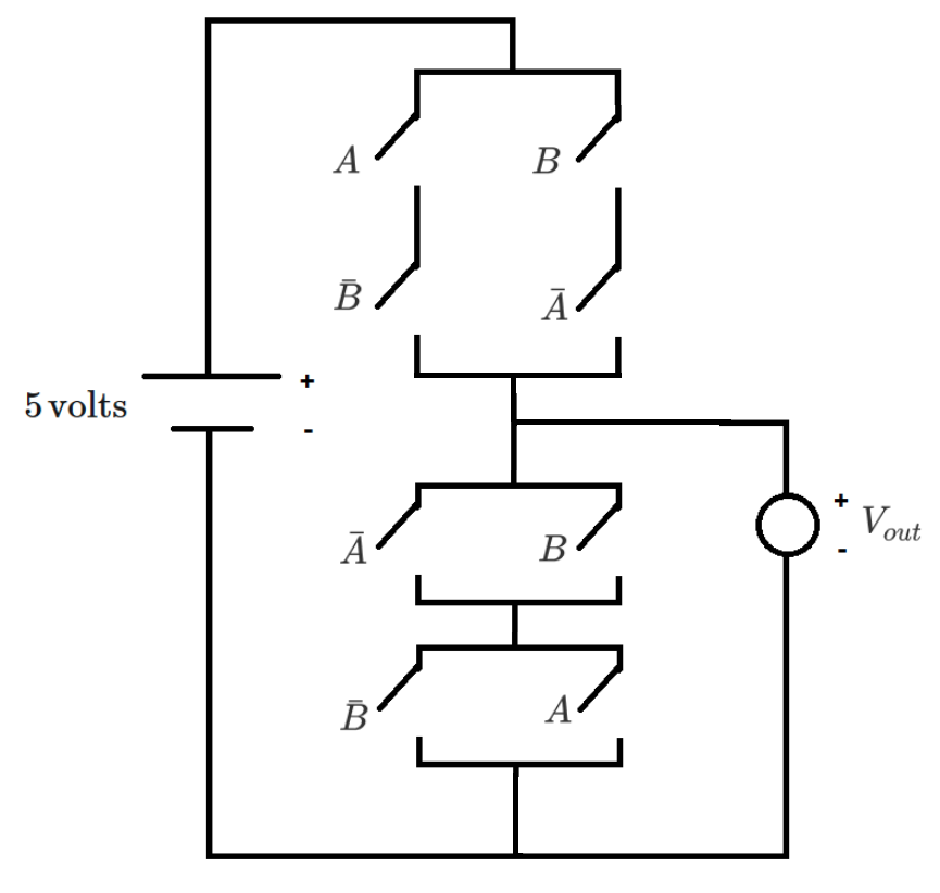
The diagram above shows a logic gate with Boolean logical inputs , and their logical negations . The source voltage is 5 volts.
corresponds to a high (true) logical output, and corresponds to a low (false) logical output. A switch is closed (conducting) if the associated logical signal is high (true), and the switch is open (non-conducting) if the associated logical signal is low (false).
Which logical operation does this gate perform?
Note: In the diagram, and look somewhat similar. Look carefully.
This section requires Javascript.
You are seeing this because something didn't load right. We suggest you, (a) try
refreshing the page, (b) enabling javascript if it is disabled on your browser and,
finally, (c)
loading the
non-javascript version of this page
. We're sorry about the hassle.
0 solutions
No explanations have been posted yet. Check back later!