Logic gates
Electricity and Magnetism
Level
2
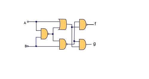
 what will be the logic level at f and g for the input pattern A = 1 and B = 1 ?
00
01
10
11
This section requires Javascript.
You are seeing this because something didn't load right. We suggest you, (a) try
refreshing the page, (b) enabling javascript if it is disabled on your browser and,
finally, (c)
loading the
non-javascript version of this page
. We're sorry about the hassle.
A = 1 and B = 1 into the leftmost NAND gate will output a C = 0.
Next, we have inputs A = 1 & C = 0 into the upper middle OR gate for an output D = 1 and inputs B = 1 & C = 0 into the lower middle NAND gate for an output E = 1.
Finally, we have inputs D = 1 & E = 1 into the upper right NAND gate for an output F = 0 and the same inputs D = 1 & E = 1 into the lower right AND gate for an output G = 1.
Answer = FG = 01