Low Pass Filter Charging Transient
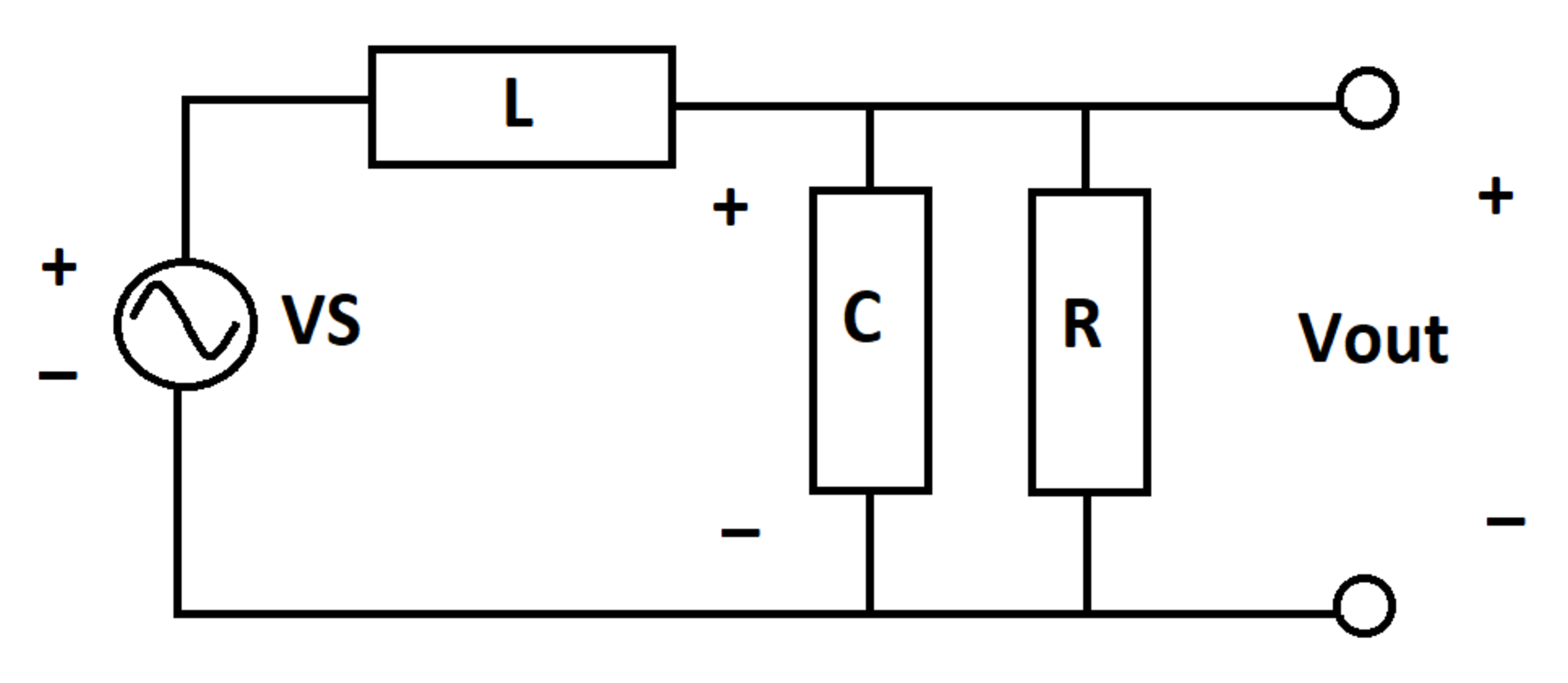
An low pass filter takes a sinusoidal voltage input and produces an output voltage .
is as follows:
Let be the steady-state output voltage signal, which can be determined using AC steady-state analysis. This function is a pure sinusoid which is scaled and shifted in time relative to . After charging transients dissipate, and converge.
At time , the inductor and capacitor are de-energized. Determine the following integral:
Details and Assumptions:
1)
2)
3)
The answer is 10.0.
This section requires Javascript.
You are seeing this because something didn't load right. We suggest you, (a) try
refreshing the page, (b) enabling javascript if it is disabled on your browser and,
finally, (c)
loading the
non-javascript version of this page
. We're sorry about the hassle.
The following solution leaves out several steps and should be thought of as a guideline.
Let the current through the inductor be I L , that through the capacitor be I C and that through the resistor be I R . Let the charge on the capacitor be Q and the output voltage be V . The circuit equations are:
I L = I C + I R ; L I ˙ L + C Q = V S ; C Q = I R R = V ; Q ˙ = I C
Initial conditions: Q ( 0 ) = 0 , I L ( 0 ) = 0 and using these conditions, those on other variables can be derived. The goal is to come up with a dynamic mapping between V S and the output V . By manipulating the above equations, the resulting differential equation is:
V ¨ + 2 V ˙ + V = 1 0 sin t
subject to: V ( 0 ) = 0 and V ˙ ( 0 ) = 0 . This differential equation can be solved using the method of Laplace transforms or any other standard approach. The closed-form solution to this is:
V = 5 e − t ( 1 + t ) − 5 cos t
From here, it can be concluded that the steady state solution is V s s = − 5 cos t and the required integral to be computed is therefore:
∫ 0 1 0 π 5 e − t ( 1 + t ) d t = 1 0 − 5 ( 1 0 π + 2 ) e − 1 0 π ≈ 1 0