LRC II

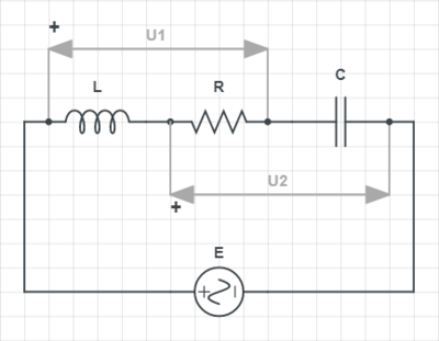
RMS values of voltages U 1 and U 2 in the AC circuit given in the schematic are 2 0 V and 1 5 V , respectively. If U 1 and U 2 are out of phase by 9 0 ° , determine the RMS value of the voltage generated by source E .
The answer is 13.892443989449804508432547041029.
This section requires Javascript.
You are seeing this because something didn't load right. We suggest you, (a) try
refreshing the page, (b) enabling javascript if it is disabled on your browser and,
finally, (c)
loading the
non-javascript version of this page
. We're sorry about the hassle.
2 solutions

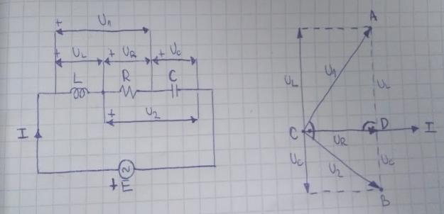
This problem can be solved using phasor diagrams . An approximate phasor diagram of this circuit is given in the picture above, where U R , U L and U C are voltages across the resistor, inductor and capacitor respectively and I is the current flowing through the circuit. If we take I as referential phasor, then:
-
U R is collinear with I , because the voltage across a resistor is in phase with the current through it
-
U L is counter-clockwise perpendicular to I and U R , because the voltage across an inductor leads the current through it by 9 0 °
-
U C is clockwise perpendicular to I and U R , because the voltage across a capacitor lags the current through it by 9 0 °
-
U R and U L sum up to U 1
-
U R and U C sum up to U 2
-
U 1 leads U 2 by 9 0 °
Points marked as A , B , C and D on the phasor diagram form three similar right-angled triangles: △ A C B , △ A D C and △ B D C . Side lengths of each of these triangles correspond to the following RMS values of voltages:
-
A C = U 1
-
B C = U 2
-
A B = U L + U C
-
A D = U L
-
B D = U C
-
C D = U R
Since A B 2 = A C 2 + B C 2 , then U L + U C = U 1 2 + U 2 2 = 2 5 V .
U R can be determined using triangle similarity:
U 1 U R = U L + U C U 2 ⇒ U R = U L + U C U 1 ∗ U 2 = 2 5 1 5 ∗ 2 0 V = 1 2 V
U L = U 1 2 − U R 2 = 2 0 2 − 1 2 2 V = 1 6 V
U C = 2 5 V − U L = 9 V
Finally, for a series RLC circuit , RMS voltage of the source is determined as:
E = U R 2 + ( U L − U C ) 2 = 1 2 2 + ( 1 6 − 9 ) 2 = 1 9 3 V ≈ 1 3 . 8 9 2 V
Just for fun, I will continue with the hill-climbing technique. This time, the program solves for four different unknown parameters ( E , X L , R , X C ) . There are three checks: one for the U 1 magnitude, one for the U 2 magnitude, and a dot product orthogonality check between U 1 and U 2 . Note that there are multiple solutions for the parameters in general, but the source voltage always ends up being 1 3 . 8 9 2 .