Maximizing the conduction
Ashish has a set of 12 resistances, each are equal in length but there resistance are in
geometric progression
. The smallest resistance is
and the common ratio is
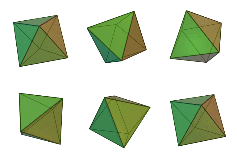
. Now, Ashish being curious boy arranged them such that the twelve resistance formed a
regular octahedron
as shown below. He also wanted the circuit to conduct maximum current. So he adjusted the resistances in a unique configuration such that equivalent resistance between a particular pair of opposite nodes is the minimum.

Now, what is the resistance that Ashish achieved for maximum conduction.
Correct your answer to two decimal places.
Try other brain storming questions like this in the set Platonic Electricity
The answer is 2.26.
This section requires Javascript.
You are seeing this because something didn't load right. We suggest you, (a) try
refreshing the page, (b) enabling javascript if it is disabled on your browser and,
finally, (c)
loading the
non-javascript version of this page
. We're sorry about the hassle.
Consider the star-mesh transformation that removes a valency 4 vertex.
If the star has resistances p , q , r , s as marked, then the equivalent mesh has resistances R U V between nodes U and V , where R U V = u v ( a − 1 + b − 1 + c − 1 + d − 1 ) U , V = A , B , C , D , U = V Here u = a , b , c , d according as U = A , B , C , D respectively, and similarly for v . If we place resistances a , b , c , d , e , f , g , h , w , x , y , z into an octahedral array, then the effective resistance between a pair of opposite vertices is the effective resistance between A and D of the combination of the following three networks:
Applying the star-mesh transformation to the two "star" networks, and combining parallel resistors, we obtain that the octahedral array is equivalent to the tetrahedral array shown left in the diagram below, where
U − 1 V − 1 W − 1 X − 1 Y − 1 Z − 1 = a d ( a − 1 + b − 1 + c − 1 + d − 1 ) 1 + w z ( w − 1 + x − 1 + y − 1 + z − 1 ) 1 = b c ( a − 1 + b − 1 + c − 1 + d − 1 ) 1 + x y ( w − 1 + x − 1 + y − 1 + z − 1 ) 1 = a b ( a − 1 + b − 1 + c − 1 + d − 1 ) 1 + e 1 + w x ( w − 1 + x − 1 + y − 1 + z − 1 ) 1 = a c ( a − 1 + b − 1 + c − 1 + d − 1 ) 1 + f 1 + w y ( w − 1 + x − 1 + y − 1 + z − 1 ) 1 = b d ( a − 1 + b − 1 + c − 1 + d − 1 ) 1 + g 1 + x z ( w − 1 + x − 1 + y − 1 + z − 1 ) 1 = c d ( a − 1 + b − 1 + c − 1 + d − 1 ) 1 + h 1 + y z ( w − 1 + x − 1 + y − 1 + z − 1 ) 1 and we can perform a Δ Y transform on the vertex B , obtaining the equivalent circuit shown on the right-hand side of the above picture, where U 1 = W Y ( V − 1 + W − 1 + Y − 1 ) X 1 = W V ( V − 1 + W − 1 + Y − 1 ) Z 1 = Y V ( V − 1 + W − 1 + Y − 1 ) Thus the effective resistance between the opposite vertices A , D is [ ( U − 1 + U 1 − 1 ) + [ ( X − 1 + X 1 − 1 ) − 1 + ( Z − 1 + Z 1 − 1 ) − 1 ] − 1 ] − 1 Running a computer programme to determine the least effective resistance of all the 1 2 ! possible arrangements of the resistances, we obtain the least resistance of 2 . 2 5 4 8 Ω for the arrangement
It is interesting to note that this optimal set-up has the four largest resistances in the equatorial ring, which has the approximate effect of insulating the longitudinal wires from each other. Thus we can approximate this optimal arrangement by a set of 3 , 1 2 , 4 8 , 1 9 2 Ω resistors in parallel, making for an approximate effective resistance of ( 3 − 1 + 1 2 − 1 + 4 8 − 1 + 1 9 2 − 1 ) − 1 = 8 5 1 9 2 = 2 . 2 5 8 8 Ω , which is a pretty close approximation to the actual value.