Multi Sine Power
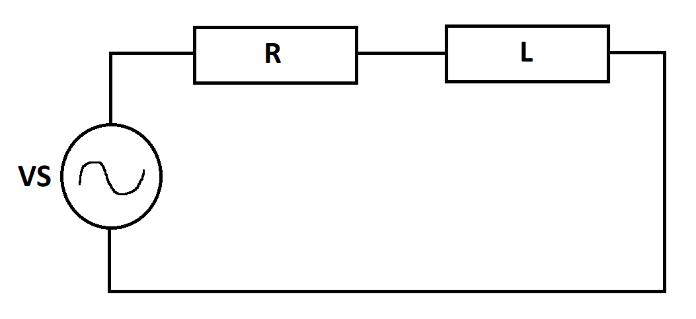
A voltage source supplies a composite voltage signal consisting of several frequencies.
V S ( t ) = 1 0 2 sin ( ω t ) + 1 0 2 sin ( 2 ω t ) + 1 0 2 sin ( 3 ω t )
The voltage source is connected across a series R L load. In steady state, what is the average power dissipated by the load (in watts)?
Details and Assumptions:
1)
ω
=
1
2
0
π
2)
R
=
1
3)
L
=
ω
1
Note: There are two ways to solve this. You can use a combination of superposition and AC steady state analysis, or you can do time-domain analysis. The two methods yield the same result. The averaging should be done over an integer number of cycles corresponding to the lowest-frequency component.

The answer is 80.0.
This section requires Javascript.
You are seeing this because something didn't load right. We suggest you, (a) try
refreshing the page, (b) enabling javascript if it is disabled on your browser and,
finally, (c)
loading the
non-javascript version of this page
. We're sorry about the hassle.
2 solutions
@Steven Chase Nice solution Upvoted.
@Steven Chase is there any analytical way to find the area of this figure
1
6
(
x
+
y
)
2
+
9
(
x
−
y
)
2
=
1
Hope I am not disturbing you.
Thanks in advance.
Log in to reply
You can read the "General Cartesian Form" section of this article to figure out what conic section it is:
https://en.wikipedia.org/wiki/Conic section#General Cartesian_form
I assume it is probably an ellipse. Then you can use the "general ellipse" section from this article to figure out the semi-major and semi-minor axis lengths. The area of the ellipse is then π a b
https://en.wikipedia.org/wiki/Ellipse#General_ellipse
@Steven Chase
in the latest problem I am not able to understand the meaning of fraction.
I am getting
ϕ
z
>
0
=
2
.
9
9
4
0
4
ϕ
z
<
0
=
0
.
7
7
5
8
7
1
Log in to reply
The problem wants the ratio of the top flux to the total flux
@Steven Chase I think you are solving 15 problems on brilliant everyday?
I took a numerical brute force approach to solve this problem. The circuit equation for this circuit is:
L I ˙ + I R = V S I ( 0 ) = 0
IN this circuit, only the resistor is capable of dissipating power. The instantaneous power dissipated by the resistor is:
P ( t ) = I ( t ) 2 R
This instantaneous power has been averaged out over a longer duration of time.
1 2 3 4 5 6 7 8 9 10 11 12 13 14 15 16 17 18 19 20 21 22 23 24 25 26 27 28 29 30 31 32 33 34 35 |
|
@Karan Chatrath By the way you were saying that in the upcoming days that i will not upload any solutions. ?
Log in to reply
Yes, I was not very active last week.
@Karan Chatrath is there any analytical way to find the area of this figure 1 6 ( x + y ) 2 + 9 ( x − y ) 2 = 1 Thanks in advance.
Log in to reply
Define u = 2 1 ( x + y ) ,and v = 2 1 ( x − y ) , then (u, v) are the coordinates of this curve in a frame that is rotated by 4 5 ∘ counter clockwise with respect to the O x y frame, and the O u v frame is an isometry of the O x y frame, i.e. they have the same scale. Now the equation in the O u v frame becomes
8 u 2 + ( 9 / 2 ) v 2 = 1
which is an ellipse with semi-major axis length of 8 = 2 2 and semi-minor axis length of 2 3 , hence the area of the ellipse is π a b = 6 π .
Log in to reply
@Hosam Hajjir
Thankyou so much.
By the way this problem is already posted in calculus section.
I will show the superposition method. I insisted on doing the time-domain analysis as a double-check, as @Karan Chatrath has shown. There are three separate frequencies in the source voltage signal, so model three separate circuits independently; one for each frequency. Add the powers from all three circuits to get the total power. The resistance value remains the same at all frequencies, but the inductive reactance changes. Calculate the inductive reactances at the different frequencies:
X 1 = ω L X 2 = 2 ω L X 3 = 3 ω L
Define the circuit impedances:
Z 1 = R + j X 1 Z 2 = R + j X 2 Z 3 = R + j X 3
Currents and voltages.
V 1 = 1 0 + j 0 V 2 = 1 0 + j 0 V 3 = 1 0 + j 0 I 1 = Z 1 V 1 I 2 = Z 2 V 2 I 3 = Z 3 V 3
Power values:
P 1 = R e ( V 1 I 1 ∗ ) = 5 0 P 2 = R e ( V 2 I 2 ∗ ) = 2 0 P 3 = R e ( V 3 I 3 ∗ ) = 1 0 P 1 + P 2 + P 3 = 8 0
The code below implements the steady state solution in the first part and the transient analysis in the second part. Both methods yield the same result.