NOT AND distributivity
Are the two circuit diagrams equivalent?
- An AND gate outputs "ON" only if both inputs are "ON." It outputs "OFF" otherwise.
- A NOT gate outputs "OFF" if the input is "ON," and vice versa.
This section requires Javascript.
You are seeing this because something didn't load right. We suggest you, (a) try
refreshing the page, (b) enabling javascript if it is disabled on your browser and,
finally, (c)
loading the
non-javascript version of this page
. We're sorry about the hassle.
15 solutions
Proving that they give different outputs for any one set of input is sufficient to prove that they are not equivalent.
Log in to reply
Yeah, except when you assume (like me, lol) that "Input" means an incoming current, or ON. xD
As a computer programmer for 35 years, I felt totally confident in answering this problem with YES. Imagine my shock when my answer came up INCORRECT! It took a few minutes to verify the validity of the input/out tables. My error? I mentally analyzed the inputs 0/0 -> 0 and 1/1 -> 1. but it did not even occur to me to check either 0/1 or 1/0. A noobie mistake.
Log in to reply
I almost made the mistake of thinking in ground-true logic of the '60s & '70s. I assume that is still the case for discrete components, which saves power. (Yes, my answer would still be 'No'.) If using the 'brute force' of the truth table for each circuit, and all possible inputs(0,0/0,1/1,0/1,1) and their corresponding outputs, and if you start from 0,0 you would have to complete at least the first two values for each circuit to find that the input of 0,0 (both->1) & then 0,1 would output 0 for cirucit #1, and 1 for circuit #2, to be sure that they are not equivalent.
Relevant wiki: De Morgan's Laws
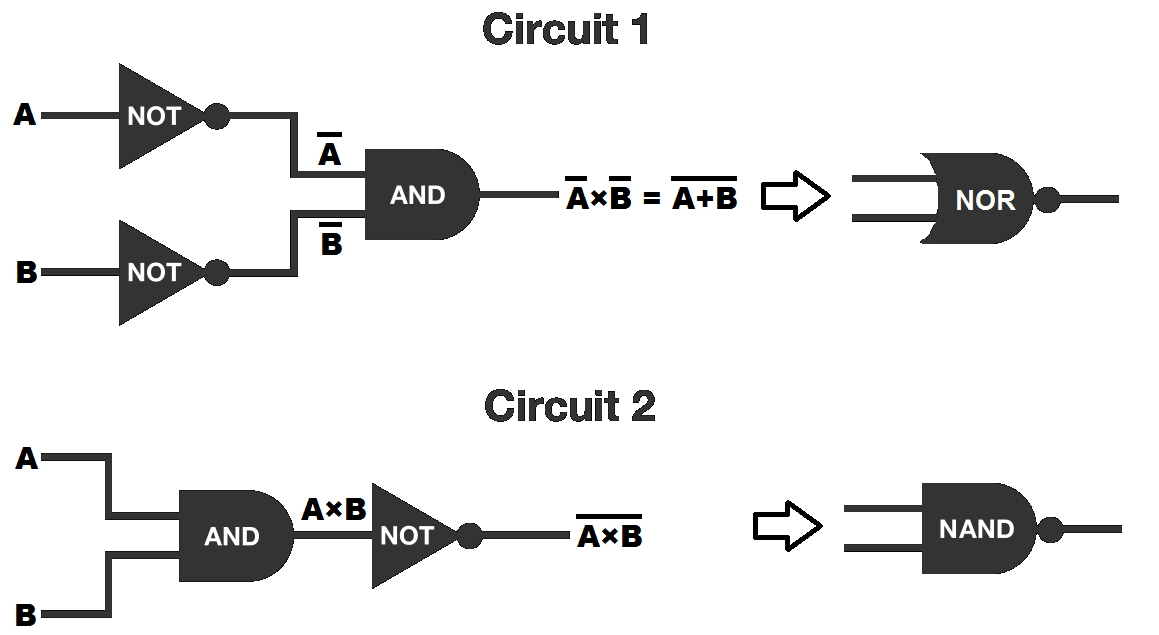
Circuit 1: The input-output table of circuit 1 is as follows:
A 0 0 1 1 B 0 1 0 1 Y 1 0 0 0
The input-output table shows that circuit 1 is equivalent to a NOR gate. In Boolean algebra Y = A × B and by De Morgan's laws , Y = A + B .
Circuit 2: The input-output table of circuit 2 is as follows:
A 0 0 1 1 B 0 1 0 1 Y 1 1 1 0
The input-output table shows that circuit 2 is equivalent to a NAND gate. In Boolean algebra Y = A × B .
Moderator note:
De Morgan's Laws can be written out with less symbols as
NOT (A AND B) is logically equivalent to NOT A OR NOT B
NOT (A OR B) is logically equivalent to NOT A AND NOT B
Our course on Logic develops them twice, once using Venn diagrams and again later with the "source code" of formal logic.
Relevant wiki: Logic Gates
First logic:
Y = A ˉ B ˉ
Second logic:
Y = A B ˉ = A ˉ + B ˉ
In the second logic, the equivalence given is due to DeMorgan's Law. The logics would thus be equivalent if the first logic had an OR gate instead of an AND gate.
Let's denote ¬ A as the negation A (i.e. NOT A).
Then, the first diagram corresponds to the logical expression ( ¬ A ) ∧ ( ¬ B ) , while the second corresponds to ¬ ( A ∧ B ) = ( ¬ A ) ∨ ( ¬ B ) , where ∧ means AND and ∨ means OR.
Then, it is easy to see that the diagrams are different from each other.
Let A , B be the two inputs. We claim that A = 1 , B = 0 , or A is true and B is false, is a counterexample to the statement that the two circuits are equivalent. The first diagram is equivalent to ¬ A ∧ ¬ B , while the second diagram is equivalent to ¬ ( A ∧ B ) . ( ¬ represents NOT, while ∧ represent AND.) We have
¬ A ∧ ¬ B = ¬ 1 ∧ ¬ 0 = 0 ∧ 1 = 0 ,
but
¬ ( A ∧ B ) = ¬ ( 1 ∧ 0 ) = ¬ 0 = 1 .
Thus, ¬ A ∧ ¬ B = ¬ ( A ∧ B ) for these truth values, so no , the two circuits are not equivalent.
It blows my mind how the solution is all this variable equational logic. I just looked at the the ending parts on each in relation to the our out and made my guess by that. I honestly am very confused on this logical explanation. This app should have videos for the answers because now I am doubting If I got the answer right because my logic was correct or because I got lucky. Because the logical explanation seems way longer and more co.plex then the way I assessed it.
Log in to reply
If you could show that the two circuits give different output for even one set of inputs, then it is sufficient to say that the two circuits are not equivalent. Steven has observed the case where A = 1 and B = 0 and written the output using formal notation.
Let's consider the fact that Circuit 2 is a classical NAND gate. With Circuit 1, if the inputs are both equivalent, they will stay equivalent after the NOT gate has been applied to them (0,0 turns to 1,1 and vice versa), and if they are not equivalent, they will stay that way after the NOT gate has been applied to them (1,0 turns to 0,1 and vice versa). With this, we deduce that Circuit 1 is a classical AND gate, which is fundamentally different from a NAND gate, and therefore the circuits are not equivalent.
Consider the possible output of the AND gate in the second circuit. There is only one pair of inputs that result in ON: ON, ON. Because of the next NOT gate, this circuit then results in OFF. There is only one way to get OFF out of the circuit.
Back to the first circuit, the AND gate is last, and there are three pairs of input that will result in OFF; all three of which are possible to output from the individual NOT gates which precede it. There really three ways to output OFF from the second gate. Therefore they are different gates.
If Input 1 and Input 2 are different, then a not gate would not have any effect on the outcome of the and gate. Once one of them goes through a not gate, it makes the outcomes different.
Suppose input 1 as X And input 2 as Y In first circuit we get final output as (X'.Y') While in second we get final output as (X'+Y') So these 2 circuits are not equivalent...
Let
INPUT 1 = A
INPUT 2 = B
In circuit 1
Z= A'.B' = (A+B)'
In circuit 2
Z= (A.B)'
THUS IN BOTH CASES Z IS NOT EQUAL SO THE TWO CIRCUITS ARE NOT EQUIVALENT
Circuit 1 is 'hard' to turn ON as you have to get both inputs right. Circuit 2 is 'easy' to turn on, because you need OFF to come out of the AND.
The first answers the question "are both inputs false?". The second answers the question "is at least one of the inputs false?".
On Circuit 1, when both of the inputs are off, the AND output is on. In Circuit 2, when both of the inputs are off or either input 1 or input 2 is on, so is the NOT output. When both of the inputs are on, it turns off the output.
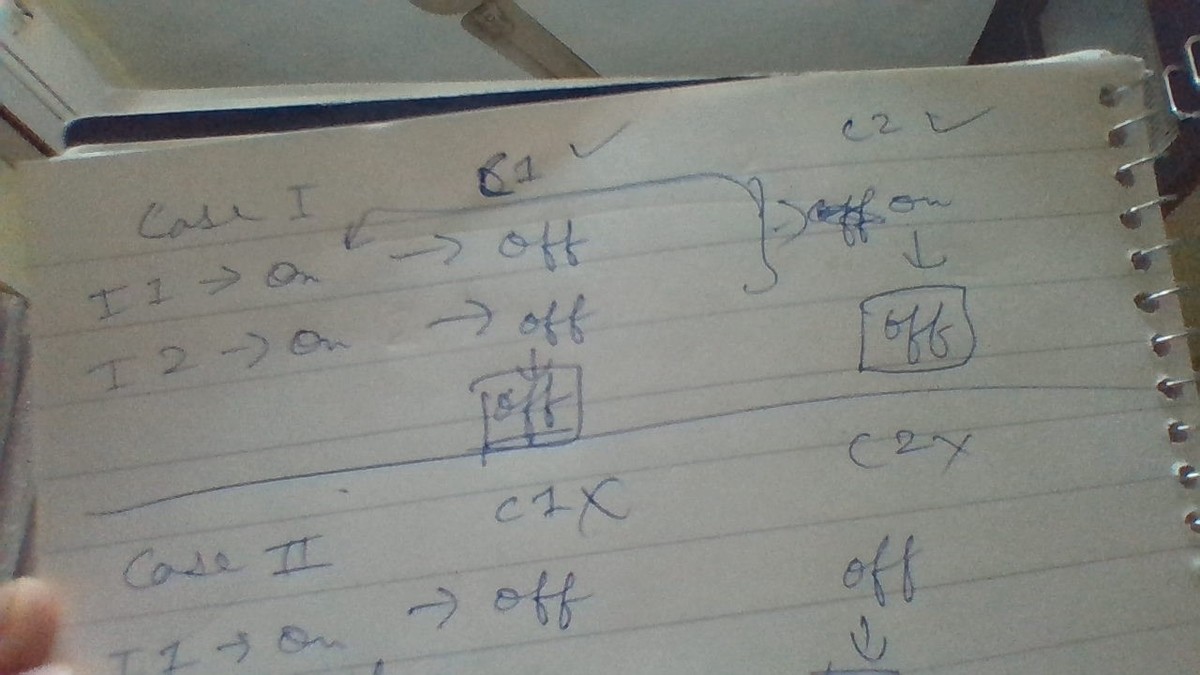
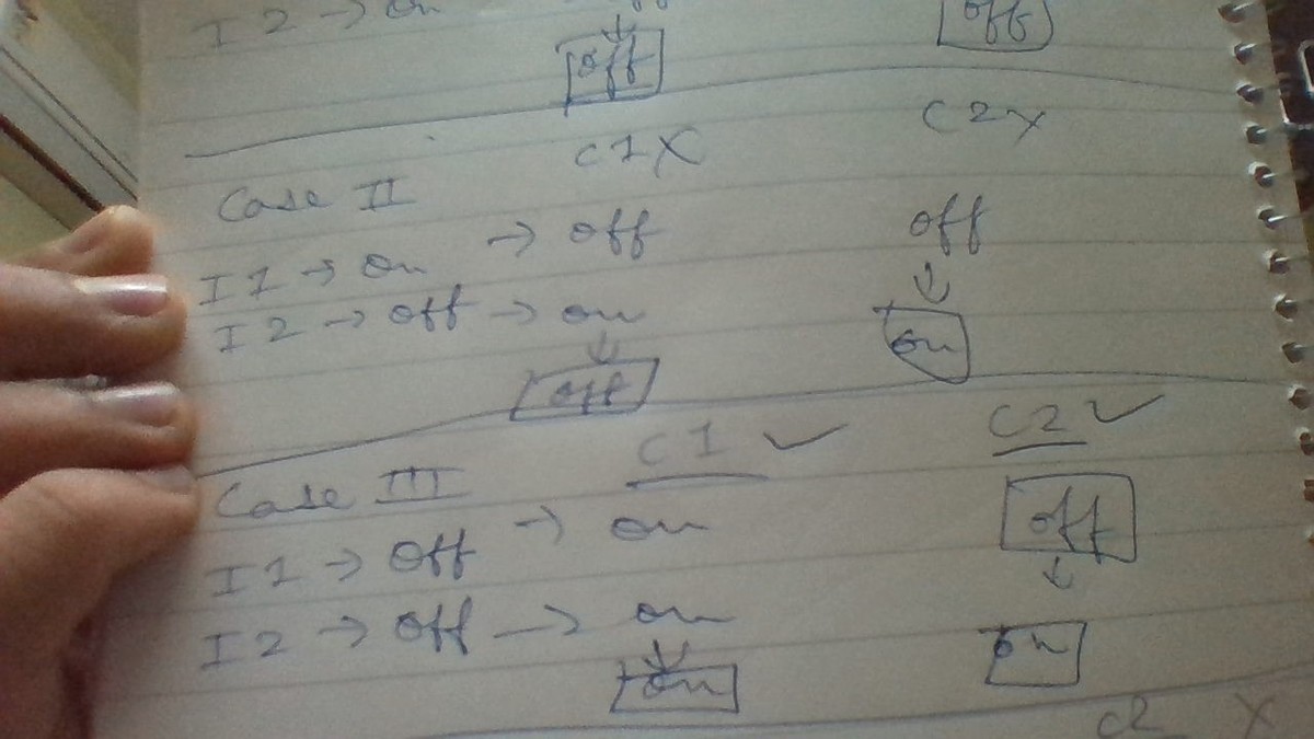
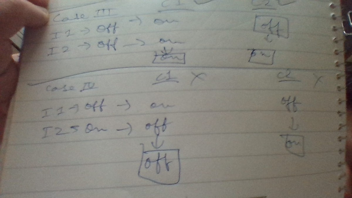
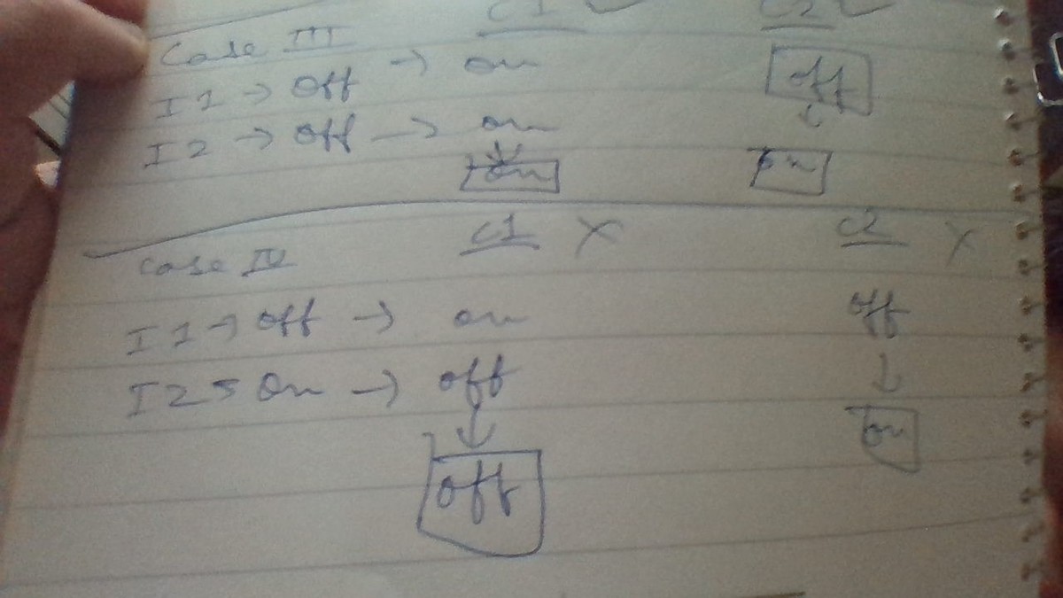
Hope that's quite simple, if you just keep the rules in mind. There's a 50-50 chance of them being alike and not depending on values of input A and B. Maths doesn't need huge formulas, just a learning brain, logic and lots of reasoning.
A great method to solve. Kindly upvote and ask if there's any doubt...
Nice analysis of all cases. Note that if we want to prove that they are not equivalent, then showing that there give different outputs for any one set of input is sufficient.
Relevant wiki: Truth Tables
An easy way to solve this is to compare input/output tables.
This makes it easy to see that they are not equivalent,