Op Amp Impedance Matching

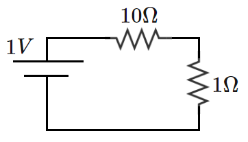
A DC voltage source with an internal resistance of is used to drive a load. Because of the source-load impedance mismatch (10 to 1), the circuit has relatively poor power transfer to the load.
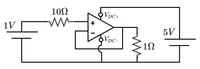
To increase the load power, a more elaborate circuit is constructed, as shown below.

The operational amplifier (op amp) used in this circuit is ideal, which means that it has the following properties:
- the voltages at the ( ) and ( ) terminals are identical;
- the currents into/out of the ( ) and ( ) terminals are zero.
The op amp has its own DC power supply.
What is the ratio of the load power in the second circuit to the load power in the first circuit?
As a bonus, what would be an appropriate name for this op amp configuration?
Note:
The curved line coming out of
indicates that an electrical connection is
not
made there with the feedback line.
The answer is 121.
This section requires Javascript.
You are seeing this because something didn't load right. We suggest you, (a) try
refreshing the page, (b) enabling javascript if it is disabled on your browser and,
finally, (c)
loading the
non-javascript version of this page
. We're sorry about the hassle.
Circuit 2: For an ideal op amp, there is no current flowing through the ( + ) and ( − ) terminals and hence no current through the internal resistance R i n = 1 0 Ω and no voltage drop across R i n . The voltage at terminal ( + ) is same as V i n = 1 V of the DC voltage source. And for an ideal op amp, voltage at ( + ) is same as that of ( − ). Therefore, the output voltage across the load 1 Ω is same as the input voltage of the DC voltage source that is 1 V . This op amp configuration is in fact called voltage follower . The load power P 2 = R L V 2 2 = 1 W .
Circuit 1: Circuit 1 is a voltage divisor. The voltage across the load V 1 = R i n + R L R L V i n = 1 1 1 ( 1 ) = 1 1 1 V and the load power P 1 = R L V 1 2 = 1 2 1 1 W .
⟹ P 1 P 2 = 1 2 1 1 1 = 1 2 1