Operational Amplifier (2)

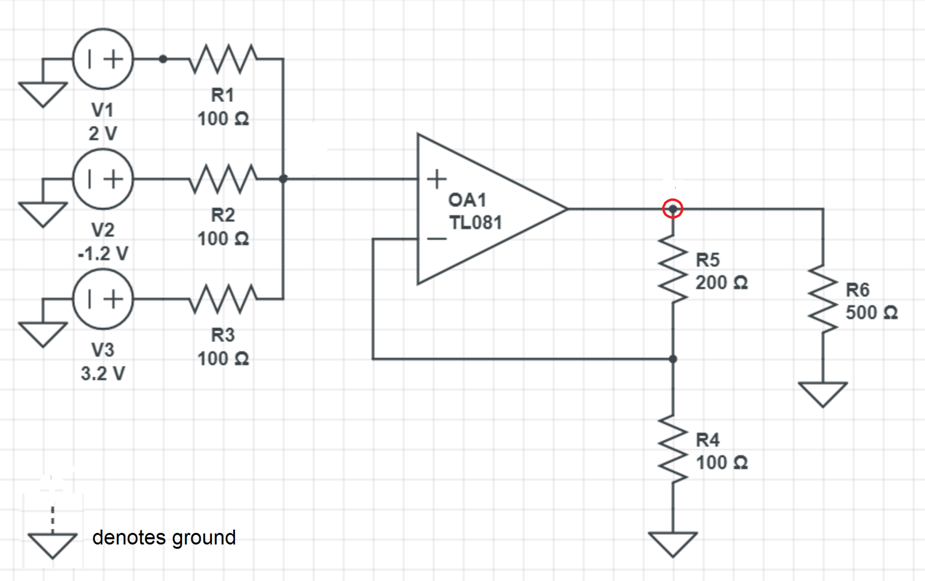
Consider the operational amplifier circuit above. What is the voltage at the node circled in V ?
Hint: Try part 1 before trying this problem.
The answer is 4.
This section requires Javascript.
You are seeing this because something didn't load right. We suggest you, (a) try
refreshing the page, (b) enabling javascript if it is disabled on your browser and,
finally, (c)
loading the
non-javascript version of this page
. We're sorry about the hassle.
2 solutions

The voltage at the node circled is the output voltage of the OpAmp V o u t . The given OpAmp circuit is a non-inverting OpAmp configuration . The closed loop voltage gain of the non-inverting OpAmp is given by:
A V V i n V o u t V o u t = R 4 R 5 + R 4 = 1 0 0 2 0 0 + 1 0 0 = 3 V i n
To find V i n , we note that the current flowing in the non-inverting input (marked "+") is zero. Then we have:
R 1 V 1 − V i n + R 2 V 2 − V i n + R 3 V 3 − V i n 1 0 0 2 − V i n + 1 0 0 − 1 . 2 − V i n + 1 0 0 3 . 2 − V i n 2 − 1 . 2 + 3 . 2 − 3 V i n ⟹ V i n = 0 = 0 = 0 = 3 4 V
Therefore, V o u t = 3 V i n = 3 × 3 4 = 4 V .
We know that the voltage at the non-inverting input is V + = 3 4 . Therefore, the voltage at the inverting input is V − = 3 4 . We also know that the current into the inverting input must be zero.
2 0 0 V − 4 / 3 + 1 0 0 0 − 4 / 3 = 0
Solving results in V = 4