Operational Amplifier (5)
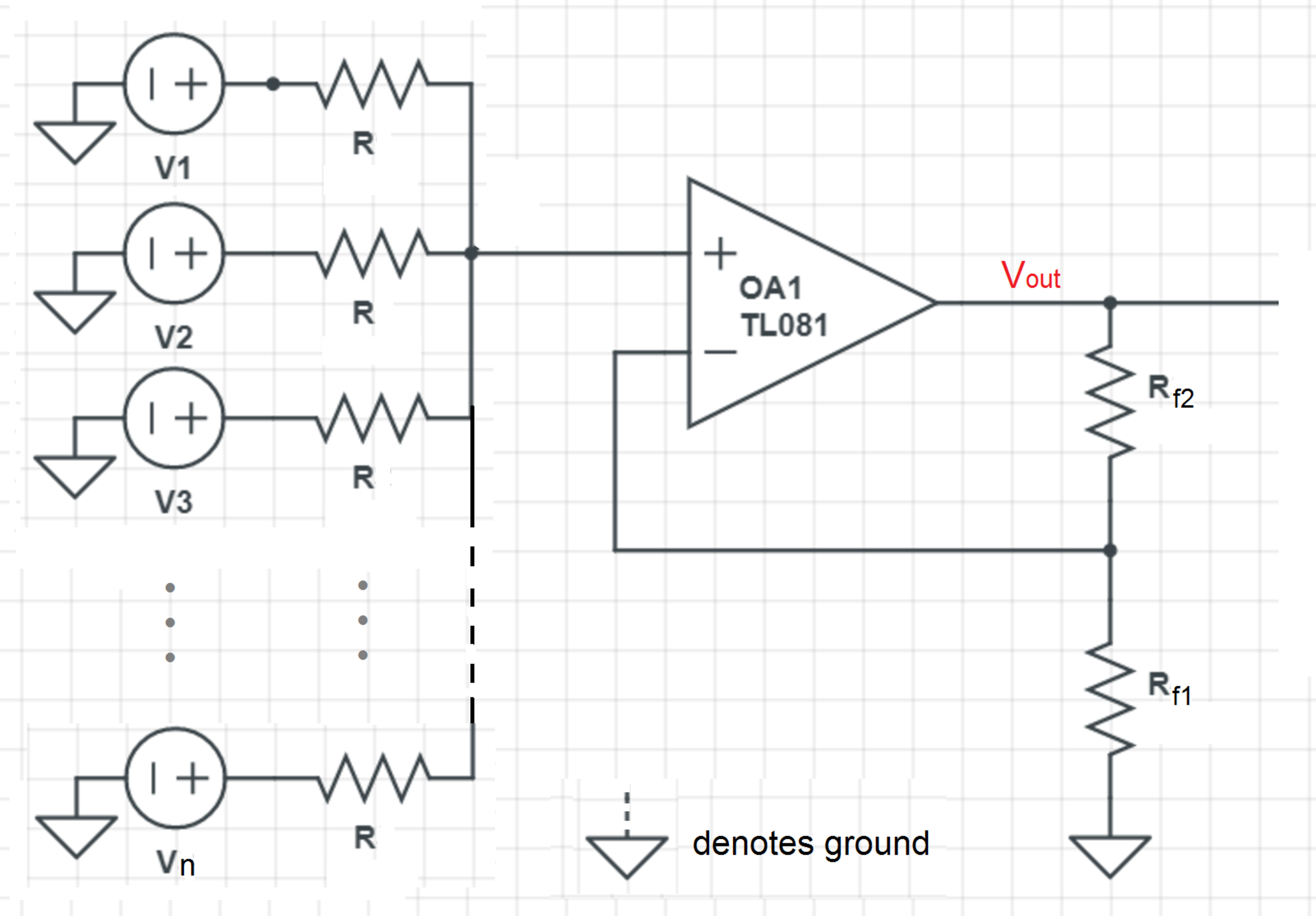
Consider the operational amplifier circuit above, where the OpAmp is connected to n input voltage sources V i each with a serial resistance R . Find R f 2 in terms of n and R f 1 such that the output voltage V o u t is the sum of the n input voltages V i .
Hint : Try part 4 before trying this problem.
This section requires Javascript.
You are seeing this because something didn't load right. We suggest you, (a) try
refreshing the page, (b) enabling javascript if it is disabled on your browser and,
finally, (c)
loading the
non-javascript version of this page
. We're sorry about the hassle.
2 solutions
This is my solution to pretty much parts 1-5 combined.
Designate the current leaving node A across R 1 , R 2 and R 3 be I 1 , I 2 and I 3 respectively. Also let the voltage at node A, which is equivalent to the voltage at the non-inverting input V + be V + . Using node-voltage analysis of node A:
By Kirchhoff's current law, since all the currents leave node A, and that no current flows into the OpAmp inputs, I 1 + I 2 + I 3 = 0 . The currents along each input branch in terms of the voltage V + :
- I 1 = R 1 V + − V 1
- I 2 = R 2 V + − V 2
- I 3 = R 3 V + − V 3
Then: R 1 V + − V 1 + R 2 V + − V 2 + R 3 V + − V 3 = 0 V + ( R 1 1 + R 2 1 + R 3 1 ) = R 1 V 1 + R 2 V 2 + R 3 V 3 V + = R 1 1 + R 2 1 + R 3 1 R 1 V 1 + R 2 V 2 + R 3 V 3
Now that we know V + , we can easier calculate the output voltage, since it's just a normal non-inverting amplifier at this point. The gain for this is G = 1 + R f 1 R f 2 , so the output voltage of the non-inverting summing amplifier is: V o u t = G × V + = ( 1 + R f 1 R f 2 ) ( R 1 1 + R 2 1 + R 3 1 R 1 V 1 + R 2 V 2 + R 3 V 3 )
If we set all the input resistances equal to each other, so R 1 = R 2 = R 3 = R for some resistance R :
V o u t = G ( R 3 R V 1 + V 2 + V 3 )
= G ( 3 V 1 + V 2 + V 3 )
Now this is looking a whole lot like summing together the input voltages!! Notice that in order to make V o u t = V 1 + V 2 + V 3 , the gain must cancel out the denominator, so the gain must equal the denominator, so G = 3 . This means that 1 + R f 1 R f 2 = 3 ⟶ R f 2 = 2 R f 1 .
Notice that the denominator of the expression for V o u t is equal to the number of input branches! This is because for every extra input branch, you get an extra R 1 on the denominator. Now you can see that this is why you want the output resistors R f 2 and R f 1 to be equal if you have two input branches; the gain must be so R f 2 = R f 1 .
We can generalize this for any number of input branches! Notice that the node voltage at node A is always V + , and no matter how many input branches you have, the sum of all the currents leaving node A through each input branch is 0 . The numerator of V + is the sum i = 1 ∑ n R i V i while the denominator is the sum of the reciprocals of the input resistances i = 1 ∑ n R i 1 . This allows us to generalize to:
V + = i = 1 ∑ n R i 1 i = 1 ∑ n R i V i
And therefore:
V o u t = G × i = 1 ∑ n R i 1 i = 1 ∑ n R i V i
Now if we set all the input resistances equal to each other, so R 1 = R 2 . . . = R for some R :
V o u t = G × R n R i = 1 ∑ n V i
= G × n i = 1 ∑ n V i
As you can see, in order for V o u t = i = 1 ∑ n V i (aka the sum of all input voltages) :
G = 1 + R f 1 R f 2 = n ⟶ R f 2 = ( n − 1 ) R f 1
@Charley Feng , I have changed the images and edited the problem statements of all the five OpAmp problems. I used Print to redo the images.
Thank you so much!
Log in to reply
You are welcome. I hope that you can learn up to do graphics.
We need to configure R f 1 and R f 2 such that V o u t = i = 1 ∑ n V i . First let us find how V i n is related to V i . We note that the current flowing into the non-inverting input (marked by "+") is zero, then we have:
R V 1 − V o u t + R V 2 − V o u t + R V 3 − V o u t + ⋯ + R V n − V o u t i = 1 ∑ n V i − n V i n ⟹ V i n = 0 = 0 = n 1 i = 1 ∑ n V i
For a non-inverting OpAmp configuration, the closed loop voltage gain is given by:
A V V i n V o u t n 1 ∑ i = 1 n V i ∑ i = 1 n V i n = R f 1 R f 2 + R f 1 = R f 1 R f 2 + R f 1 = R f 1 R f 2 + R f 1 = R f 1 R f 2 + R f 1 Putting V o u t = i = 1 ∑ n V i and V i n = n 1 i = 1 ∑ n V i
Therefore the answer is R f 2 = ( n − 1 ) R f 1 .