Paralleled Transformers
An AC voltage source feeds a bus through a set of paralleled step-up transformers, as shown in the diagram. The transformers are modeled as impedances in series with ideal transformer windings, with turns ratios as indicated. The source impedance is also shown.
Even though the high-side bus is unloaded (open), the transformers draw current because they have uneven turns ratios and impedances.
What is the magnitude of the current flowing through the impedance?
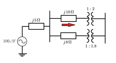
The answer is 0.60496.
This section requires Javascript.
You are seeing this because something didn't load right. We suggest you, (a) try
refreshing the page, (b) enabling javascript if it is disabled on your browser and,
finally, (c)
loading the
non-javascript version of this page
. We're sorry about the hassle.
The easiest way to solve this problem is to turn the two transformers into a single lumped element with well defined voltage and current ratios.
Another way to see it is to think of the 1 : 2 and 1 : 1 . 8 transformers are transformers feeding into each other, so that you get a turns ratio of 1 : 2 to 1 . 8 : 1 or a turns ratio of 1 . 8 : 2 . If we denote the voltage at the primary side for the 1 : 2 as V 1 and the voltage of the primary side for the 1 : 1 . 8 as V 2 , we have V 1 : V 2 = 1 . 8 : 2 or 9 : 1 0 .
Since ideal transformers are energy conserving (doesn't give you more or less power than you put in) the current ratios must be the reciprocal of the turns ratios so I 1 : I 2 = 1 0 : 9 . There is a phasing issue to remember too, so current in at primary side at the top comes out at primary side at the bottom transformer (flowing back to the j 8 Ω towards the source).
Now, we just apply the KVL and KCL rules to solve the rest of the circuit.
Let's use KCL first. To make things simpler, just call the current I 1 = 9 j 1 0 I and I 2 = − j 1 I so the source current is just 9 j 1 I . The complex part is just to make the calculation easier since all impedances are imaginary.
Now, apply KVL to the branches, ending with V 1 and V 2 , and noting that V 1 = 1 0 9 V 2 .
(1) top branch 1 0 0 − ( j 5 ) ( j 9 1 ) I − ( j 1 0 ) ( 9 j 1 0 ) I − V 1 = 0
(2) bottom branch 1 0 0 − ( j 5 ) ( j 9 1 ) I + ( j 8 ) ( j 1 ) I − V 2 = 0 <- replace V 2 with 9 1 0 V 1
After some rearranging we get
(1) 1 0 5 I + 9 V 1 = 9 0 0
(2) 6 7 I − 1 0 V 1 = − 9 0 0
I = ( 1 0 5 ) ( 1 0 ) + ( 6 7 ) ( 9 ) ( 9 0 0 ) ( 1 0 ) − ( 9 0 0 ) ( 9 ) = 1 6 5 3 9 0 0
And we also obtain I 1 as 9 1 0 I = 1 6 5 3 1 0 0 0 ≈ 0 . 6 0 4 9 6