Poly Bridge
A simple bridge of three triangular elements spans a river and is carried by the foundation at A and C in the diagram. The connecting lines between the points correspond to steel girders, each of which can bear a maximum tensile and compressive load of 10 tons.
What is the minimum angle α needed so that a truck with a weight of 10 tons can safely cross the bridge?
Hints:
- Assume that the weight load of the truck is concentrated at point B , so here a force of F B = ( 1 0 tons ) ⋅ g acts on the bridge.
- The bridge is held by the opposing forces F A = F C = − 2 1 F B on points A and C . Calculate the forces acting along the steel girders.
Note: for every point of the polygon, the sum of all forces must be zero.
This section requires Javascript.
You are seeing this because something didn't load right. We suggest you, (a) try
refreshing the page, (b) enabling javascript if it is disabled on your browser and,
finally, (c)
loading the
non-javascript version of this page
. We're sorry about the hassle.
3 solutions
Sir I am not able to understand how the force on A can have a component along its perpendicular.can you help me to find out where I am wrong.
Log in to reply
Keep in mind this problem is symmetric. Force at B implies force on truss at BD, which implies force on truss AD (because there is no vertical component to truss DE) which implies force on truss AB. AB is horizontal truss therefore horizontal force at point A.
You have ac=ce it should be ad=ce
The maximum bending moment in the entire structure will be M=P•Length-of-bridge/4. The resisting moment midspan will be M=Compression-in-top-chord•Height-of-truss. Setting these equal, and since P and C are the same value, this reduces to Height=Length/4. The bridge length can easily be divided into 4 units at the joints. The only way the first joint can be a distance of L/4 both up and over is if the first angled chord is at 45°.
Sorry but i didn't understand if the truck passes the bridge throught A,B,C or A,D,E,C. Are you sure is it clear with the inital statement?
I solved the problem using a 'reciprocal diagram'. I believe this approach to frame-like structures was worked out by James Clerk Maxwell in the 1 9 t h century. My apologies for the clunky diagrams. Maybe someone can suggest a good (free) package for drawing geometrical figures?
I assume that all the internal forces lie along the lines of the struts.
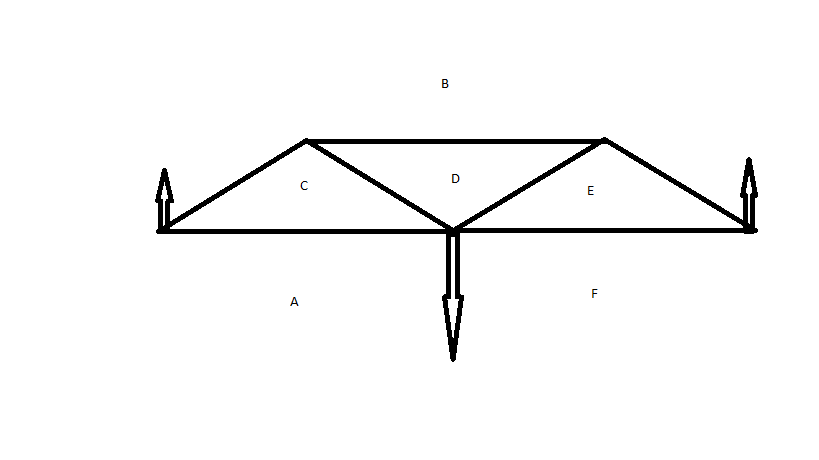
First of all label the regions of the diagram like this

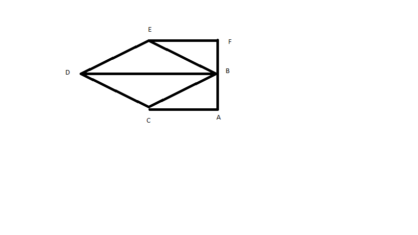
This allows us to draw the reciprocal diagram like this:-

In this diagram the vertices carry the same labels as the regions in the first diagram. A line segment like EF represents the force which separates the two areas on either side of the force, in this case E and F, that is the force in the bottom right hand strut. The line segments are drawn parallel to the actual forces and their lengths are proportional to the magnitude of the forces. The diagram is constructed so that the forces acting at each point form a closed polygon, which is a necessary condition for equilibrium. You will notice that the load and the reaction forces form a triangle of zero area because the forces are parallel. With a bit of juggling (it gets easier with practice!) everything works out like a jigsaw puzzle, even although we don't yet know the actual value of α or the magnitudes of the internal forces.
The longest line in the diagram representing an internal force is DB (which represents the tension in the top strut). Setting the known reaction force FB to 5 and DB to 10 (its maximum permitted value), noticing that by a symmetry inherited from the first diagram E lies above the midpoint of DB, and recognising that the angle we want is EDB, it is easy to see that dropping a perpendicular from E to DB forms a right angled isosceles triangle, and so α = 4 5 o
Notice that if the angle is less than 45 degrees, DB becomes greater than 10 units, which is why we can say that 45 degrees is the minimum angle for an uncollapsed structure.
As an example, consider the balance of forces at the point A . Along the connecting elements act the forces f A B and f A D , which must add to zero with the outer force F A . Geometrically, this means that the vector arrows correspond to the sides of a right-angled triangle of forces. Since the force F A corresponds to the leg opposed to α , it follows f A B = F A / tan α for the other leg and f A D = F A / sin α for the hypotenuse.
Calculating the balance of forces for all other points, the following forces finally result: f A B f A C f B D f D E = f B C = − 2 tan α 1 F B = f C E = 2 sin α 1 F B = f B E = − 2 sin α 1 F B = tan α 1 F B
Here, the signs are chosen so that positive forces corresonds to tensile loads and negative forces correspond to compressive loads. Since the steel girders are designed for a maximum load of 10 tons, ∣ f i ∣ ≤ F B must apply. This leads to the equations
sin α ≥ 2 1 , tan α ≥ 1 ⇒ α ≥ 4 5 ∘