Power Export with Fault
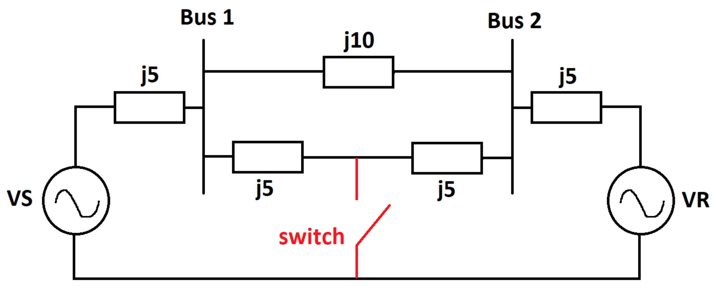
Two AC voltage sources and feed an inductive network as shown. The inductive impedance values are shown in the diagram. There is an ideal switch shown in red. Let be the active power supplied by with the switch open, and let be the active power supplied by with the switch closed.
What is ?
Details and Assumptions:
1)
2)
3)
Assume standard
units for all quantities. The unit of
active power
is the Watt.
4)

The answer is 0.25.
This section requires Javascript.
You are seeing this because something didn't load right. We suggest you, (a) try
refreshing the page, (b) enabling javascript if it is disabled on your browser and,
finally, (c)
loading the
non-javascript version of this page
. We're sorry about the hassle.
Each of the impedances are labelled in the diagram above.
Case 1: When the switch is open: The equivalent impedance of the circuit is:
Z = Z 1 + Z 2 + Z 3 + Z 4 Z 2 ( Z 3 + Z 4 ) + Z 5
Current flowing through source V S is:
I 1 = Z V S − V R ⟹ P 1 = r e a l ( V S I 1 ∗ )
Case 2: When the switch is closed: The currents flowing through each impedance Z i is I i . The current flowing through the closed switch is I 6 . Based on this, the circuit equations can be derived using Kirchoff's laws of voltage and current, and written in a matrix form as follows:
⎣ ⎢ ⎢ ⎢ ⎢ ⎢ ⎢ ⎡ 1 0 0 0 Z 1 Z 1 − 1 0 1 − Z 2 0 Z 2 − 1 1 0 Z 3 Z 3 0 0 − 1 1 Z 4 0 0 0 0 − 1 0 0 Z 5 0 − 1 0 0 0 0 ⎦ ⎥ ⎥ ⎥ ⎥ ⎥ ⎥ ⎤ ⎣ ⎢ ⎢ ⎢ ⎢ ⎢ ⎢ ⎡ I 1 I 2 I 3 I 4 I 5 I 6 ⎦ ⎥ ⎥ ⎥ ⎥ ⎥ ⎥ ⎤ = ⎣ ⎢ ⎢ ⎢ ⎢ ⎢ ⎢ ⎡ 0 0 0 0 V S V S − V R ⎦ ⎥ ⎥ ⎥ ⎥ ⎥ ⎥ ⎤ ⟹ A I = b ⟹ I 1 = [ 1 0 0 0 0 0 ] A − 1 b ⟹ P 2 = r e a l ( V S I 1 ∗ )
Finally:
P 1 P 2 = 0 . 2 5
Calculations have been left out of this solution but steps are provided.