Power Factor Correction (Multi-Valued)

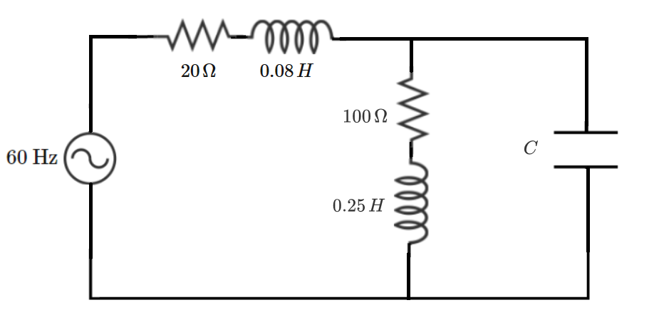
An ideal AC voltage source supplies a composite RLC load, as shown above. There are two possible values of capacitance, and , which give the load unity power factor.
What is (in microfarads)?
Note: All RLC components in the diagram above count as being part of the load.
The answer is 114.4318.
This section requires Javascript.
You are seeing this because something didn't load right. We suggest you, (a) try
refreshing the page, (b) enabling javascript if it is disabled on your browser and,
finally, (c)
loading the
non-javascript version of this page
. We're sorry about the hassle.
A parameter sweep is the easiest way to solve this problem, but just for fun, let's derive a formal solution. Based on the notation in the picture above, we expect the capacitor reactance to turn out negative.
Intermediate parallel impedance:
Z P = R 2 + j ( X + X 2 ) j X ( R 2 + j X 2 ) = R 2 + j ( X + X 2 ) j X ( R 2 + j X 2 ) ⋅ R 2 − j ( X + X 2 ) R 2 − j ( X + X 2 )
Reactive part of parallel impedance:
X P = R 2 2 + ( X + X 2 ) 2 X R 2 2 + X X 2 ( X + X 2 )
Equating this to the negative of the series inductive reactance:
X 1 ( R 2 2 + ( X + X 2 ) 2 ) = − X R 2 2 − X X 2 ( X + X 2 ) X 1 ( R 2 2 + X 2 + 2 X X 2 + X 2 2 ) = − X R 2 2 − X 2 X 2 − X 2 2 X X 1 R 2 2 + X 1 X 2 + 2 X X 1 X 2 + X 1 X 2 2 = − X R 2 2 − X 2 X 2 − X 2 2 X
Getting the equivalence expression into a quadratic form in X :
X 2 [ X 1 + X 2 ] + X [ R 2 2 + X 2 2 + 2 X 1 X 2 ] + X 1 ( R 2 2 + X 2 2 ) = 0
Results of quadratic solution:
X = − 2 6 . 8 2 4 1 Ω X = − 1 7 0 . 6 5 2 9 Ω C 1 = 9 8 . 8 8 8 0 μ F C 2 = 1 5 . 5 4 3 7 μ F