Pulley Logic by Fernando da Vinci

Fernando da Vinci, one of the famed Leonardo’s many and little-known half-brothers, has left behind drawings of ingenious mechanisms involving pulleys, ropes, and springs. Historians and engineers were able to recreate his drawings using modern notation and translated into English, as shown as in this graphic, showing 7 distinct and separate mechanisms and their frames.
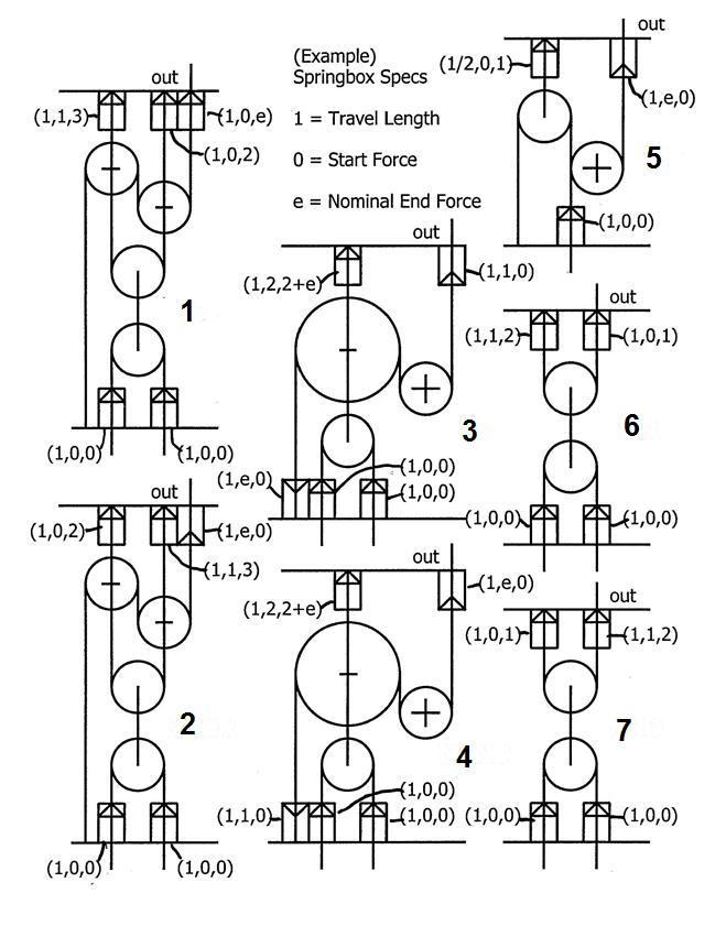
They realize now that entirely by pulley, rope and spring action, these mechanisms functioned as logic gates! Four centuries before digital computers! But they first had to figure out and make the following assumptions:

Pulleys

Circles of radii 1 1 and 2 2 represent pulley wheels. A + sign in the center of a circle indicates that the pulley’s axle is fixed in the frame space. A vertical line terminating in the center of a center indicates that the pulley’s axle is tethered to the end of a rope but otherwise free to move with the rope. A sign in the center of a circle with a vertical line running through it indicates that the pulley’s axle is tethered to the length of a rope at that point, but likewise otherwise free to move with the rope.

Ropes

Vertical lines represent flexible ropes, which may be 1) fixed to the frame, 2) tethered to the axle of a pulley wheel, 3) fixed to the end of a spring in a spring cage, or 4) passing either through the frame from the bottom or through the top of the frame. Where the diagrams suggests, ropes may pass around a pulley wheel, and in figure 5 5 in particular, 2 2 ropes pass around the top pulley wheel, one terminating in a spring cage at the bottom of the frame, the other passing around the pulley that has a fixed axle.

Spring Cages

Small rectangular boxes with arrows inside represent a spring assembly, through the center of which passes a rope. The rope is attached to the spring where the arrows are, and such arrows are free to move, constrained by the force of the spring. The arrows indicate the direction of the spring force. The travel of the arrow (and the rope affixed to it) is limited by the length of the spring cage. If the arrow is shown “sitting at the bottom of a spring cage”, it indicates that tension in the rope is already pulling the arrow down to the limit of its travel in the spring cage, in the initial state of that assembly of pulleys, ropes, and spring cages

Spring Forces in Cages

Each spring cage has characteristics which is represented by a tuple ( a , b , c ) (a, b, c) , where

a \; indicates the maximum length of travel of the arrow
b \; indicates spring force in the initial position, in the arrow’s direction
c \; indicates spring force in the final position, after maximum travel of the arrow

A tuple of ( 1 , 0 , 0 ) (1,0,0) means there’s no spring, even though travel is still limited. A value of e e means a nominal figure 1 e > 0 1\gg e>0 .

Input and Output

The rope(s) passing through the bottom of the frame represents the input(s), while the rope passing through the top of the frame (where marked as “out”) represents the output. All input and output rope travel length is limited to 1 1 , and they are either in the down position, representing the 1 logic state, or they are in the up position, representing the 0 logic state. If the output rope travels from up to down position, then it has gone from logic state 0 to logic state 1 , and likewise if it travels from down to up position, then it has gone from logic state 1 to logic state 0 . It is assumed that there will always be some nominal tension on the output rope.

Given the following list of logic gates in order from 1 1 through 7 7

1) \; NOT
2) \; AND
3) \; OR
4) \; XOR
5) \; NAND
6) \; NOR
7) \; XNOR

list the Figure numbers of the mechanisms which function correspond with these logic gates in the same order, and give your answer as a 7 7 digit number.

See Logic Gates

Note Coiled springs first appeared as early as 15th century
Also, this is a made up story but the problem is still real


The answer is 5761432.

This section requires Javascript.
You are seeing this because something didn't load right. We suggest you, (a) try refreshing the page, (b) enabling javascript if it is disabled on your browser and, finally, (c) loading the non-javascript version of this page . We're sorry about the hassle.

3 solutions

Jonathan Quarrie
May 1, 2017

Logic Gates.

As we can see below, the default state (0 input) of any logic gate can be either O n \color{#20A900}On ( 1 \color{#20A900}1 ) or O f f \color{#D61F06}Off ( 0 \color{#D61F06}0 )

The set of unknown mechanisms that are O n \color{#20A900}On (down) by default is (2,3,4,5).

The set of unknown mechanisms that are O f f \color{#D61F06}Off (up) by default is (1,6,7)

Order Gate Input 1 Output Mechanism Set
1 N O T \color{#20A900}NOT 0 1 \color{#20A900}1 (2,3,4,5)
1 NOT 1 0
Order Gate Input 1 Input 2 Output Mechanism Set
2 A N D \color{#D61F06}AND 0 0 0 \color{#D61F06}0 (1,6,7)
2 AND 0 1 0
2 AND 1 0 0
2 AND 1 1 1
Order Gate Input 1 Input 2 Output Mechanism Set
3 O R \color{#D61F06}OR 0 0 0 \color{#D61F06}0 (1,6,7)
3 OR 0 1 1
3 OR 1 0 1
3 OR 1 1 1
Order Gate Input 1 Input 2 Output Mechanism Set
4 X O R \color{#D61F06}XOR 0 0 0 \color{#D61F06}0 (1,6,7)
4 XOR 0 1 1
4 XOR 1 0 1
4 XOR 1 1 0
Order Gate Input 1 Input 2 Output Mechanism Set
5 N A N D \color{#20A900}NAND 0 0 1 \color{#20A900}1 (2,3,4,5)
5 NAND 0 1 1
5 NAND 1 0 1
5 NAND 1 1 0
Order Gate Input 1 Input 2 Output Mechanism Set
6 N O R \color{#20A900}NOR 0 0 1 \color{#20A900}1 (2,3,4,5)
6 NOR 0 1 0
6 NOR 1 0 0
6 NOR 1 1 0
Order Gate Input 1 Input 2 Output Mechanism Set
7 X N O R \color{#20A900}XNOR 0 0 1 \color{#20A900}1 (2,3,4,5)
7 XNOR 0 1 0
7 XNOR 1 0 0
7 XNOR 1 1 1

The following table identifies the Logic Gates in Order, and lists the possible Mechanisms each logic gate may have at each stage of deduction.

Order 1 2 3 4 5 6 7
Gate N O T \color{#20A900}NOT A N D \color{#D61F06}AND O R \color{#D61F06}OR X O R \color{#D61F06}XOR N A N D \color{#20A900}NAND N O R \color{#20A900}NOR X N O R \color{#20A900}XNOR
Mechanisms (2,3,4,5) (1,6,7) (1,6,7) (1,6,7) (2,3,4,5) (2,3,4,5) (2,3,4,5)

A N O T \color{#20A900}NOT gate only has one input, so that must be mechanism 5.

Order 1 2 3 4 5 6 7
Gate N O T \color{#20A900}NOT A N D \color{#D61F06}AND O R \color{#D61F06}OR X O R \color{#D61F06}XOR N A N D \color{#20A900}NAND N O R \color{#20A900}NOR X N O R \color{#20A900}XNOR
Mechanisms (5) (1,6,7) (1,6,7) (1,6,7) (2,3,4) (2,3,4) (2,3,4)

Mechanisms 1 and 2 go through two state changes between incrementing inputs:

  • Zero input = default state
  • One (either) input = state change
  • Two (both) inputs = state change

This is because the only comparable spring cages are at the top of the mechanism (1,0,2) and (1,1,3), and affect the height of the '-' pulleys. The relative distance between the '-' pulleys dictates the 'out' state.

One input changes the relative distance between the '-' pulleys, and then both inputs brings them back to the original relative distance apart.

The X O R \color{#D61F06}XOR and X N O R \color{#20A900}XNOR logic gates match these mechanisms. As they have different default states, we just need to assign the mechanisms based on their starting position.

  • Mechanism 1's default position = O f f \color{#D61F06}Off
  • Mechanism 2's default position = O n \color{#20A900}On
Order 1 2 3 4 5 6 7
Gate N O T \color{#20A900}NOT A N D \color{#D61F06}AND O R \color{#D61F06}OR X O R \color{#D61F06}XOR N A N D \color{#20A900}NAND N O R \color{#20A900}NOR X N O R \color{#20A900}XNOR
Mechanisms (5) (6,7) (6,7) (1) (3,4) (3,4) (2)

The remaining logic gates in both sets have the same differences - One gate will have a state change with at least one input, and the other gate will only have a state change with two inputs. So we need to put some thought into how the mechanisms work to make the distinction.

The rule I used was (with respect to incrementing inputs):

The rope in the spring cage with the greatest initial directional force (compared to its opposing end) does one of two things; \small \color{#3D99F6}\text{The rope in the spring cage with the greatest initial directional force (compared to its opposing end) does one of two things;}

  • Moves in the direction of its force first, \small \color{#3D99F6}\text{Moves in the direction of its force first,}

  • Or moves away from the direction of its force last. \small \color{#3D99F6}\text{Or moves away from the direction of its force last.}

  • Moving first equates to one input (either).
  • Moving last equates to two inputs (both).

(I could have been using this rule from the outset, but I didn't need to until now.)

With this logic, we can determine the following:

Mechanisms 3 and 4 Mechanisms 3 and 4

  • Mechanism 3
    • Default position = O n \color{#20A900}On
    • The 'out' spring cage (1, 1 ,0) has a force greater than its opposing end (1, e ,0).
    • The rope in the 'out' spring cage can only move in the direction of its force, so it will move first.
    • So a state change will occur with at least one input into the system.
    • N O R \color{#20A900}NOR matches this logical system.
  • Mechanism 4
    • Default position = O n \color{#20A900}On
    • The 'out' spring cage (1, e ,0) has a force less then its opposing end (1, 1 ,0).
    • The rope in the 'out' spring cage can only move in the direction of its force, so it will move last.
    • So a state change will only occur with two inputs into the system.
    • N A N D \color{#20A900}NAND matches this logical system.
Order 1 2 3 4 5 6 7
Gate N O T \color{#20A900}NOT A N D \color{#D61F06}AND O R \color{#D61F06}OR X O R \color{#D61F06}XOR N A N D \color{#20A900}NAND N O R \color{#20A900}NOR X N O R \color{#20A900}XNOR
Mechanisms (5) (6,7) (6,7) (1) (4) (3) (2)

Mechanisms 6 and 7 Mechanisms 6 and 7

  • Mechanism 6
    • Default position = O f f \color{#D61F06}Off
    • The 'out' spring cage (1. 0 .1) has a force less than its opposing end (1, 1 ,2).
    • The rope in the 'out' spring cage can only be pulled away from the direction its force, so will move first.
    • So a state change will occur with at least one input into the system.
    • O R \color{#D61F06}OR matches this logical system.
  • Mechanism 7
    • Default position = O f f \color{#D61F06}Off
    • The 'out' spring cage (1, 1 ,2) has a force greater than its opposing end (1, 0 ,1).
    • The rope in the 'out' spring cage can only be pulled away from the direction its force, so will move last.
    • So a state change will only occur with two inputs into the system.
    • A N D \color{#D61F06}AND matches this logical system.
Order 1 2 3 4 5 6 7
Gate N O T \color{#20A900}NOT A N D \color{#D61F06}AND O R \color{#D61F06}OR X O R \color{#D61F06}XOR N A N D \color{#20A900}NAND N O R \color{#20A900}NOR X N O R \color{#20A900}XNOR
Mechanisms (5) (7) (6) (1) (4) (3) (2)

5761432 \large \boxed{5761432}

This is awesome, Jonathan. I can't thank you enough for this.

Michael Mendrin - 4 years, 1 month ago

Log in to reply

Thank you for such a great problem! It's the first Mechanics problem I've ever tried, so I just hope it was sufficiently explained.

Jonathan Quarrie - 4 years, 1 month ago

Log in to reply

Oh it was certainly sufficiently explained. I suspect that many stumble over how the spring cages work and affect the logic, and you've carefully explained this in detail.

Michael Mendrin - 4 years, 1 month ago
Steve Smith
Jan 10, 2020

I don’t know what the question is. I just randomly thought some number and typed it. The answer is exactly correct

K T
Jan 25, 2019

What a great problem, thanks for contributing! Nice to learn about Fernando da Vinci and that he too was centuries ahead of his time!

(Figure 1) pulling either input string with force F pulls the lower two pulleys down with force 2F. Each of the upper pulleys then is pulled down with force F. They each may move down over a distance 1, against a spring force. The rightmost (1,0,2) spring has no initial tension, so it will move down first, tightening the output rope. When F=1, that spring box is halfway, the (1,1,3) box is still up, and the output box is already fully down. When both inputs are down however, both pulleys will be down and the output string is relaxed again. The truth table is that of XOR:

input 1 input 2 output
0 0 0
1 0 1
0 1 1
1 1 0

(Figure 2) The only difference with (1.) are the spring cages at the top. The (1,0,2) box now is connected to the leftmost pulley, so that the output rope is not tightened, but loosened when either input rope is pulled. Output is initially down, corresponding to a NXOR:

input 1 input 2 output
0 0 1
1 0 0
0 1 0
1 1 1

(Figure 3)  Initially, the output string tension is 1, the big pulley is pulled down by twice that, up by the upper left spring box (also 2). When pulling either input string, the top spring will yield so that the big pulley lowers, relaxing the output string. The output spring (1,1,0) pulls harder on it than the other end (1,e,0), so it will take its chance to go up (0). When both inputs are down, the output string is relaxed even more, which does not alter the output. This is a NOR gate.

input 1 input 2 output
0 0 1
1 0 0
0 1 0
1 1 0

(Figure 4) Similar, but here the output and lower left spring boxes have swapped characteristics. This is a NAND gate.

input 1 input 2 output
0 0 1
1 0 1
0 1 1
1 1 0

(Figure 5) Pulling the input with force F causes 2F at the left top box. So that box is fully down when 2F=1. The fixed pulley inverts the input, so this is a NOT gate.

(Figure 6) If one of the inputs is down, the pulleys are halfway down. The output is the first to go down, this is an OR gate.

input 1 input 2 output
0 0 0
1 0 1
0 1 1
1 1 1

(Figure 7) If one of the inputs is down, the pulleys are halfway down. The output is the last to give in, this is an AND gate.

input 1 input 2 output
0 0 0
1 0 0
0 1 0
1 1 1

Listing the figure numbers in the given order:

1)  NOT -> 5

2)  AND -> 7

3)  OR   -> 6

4)  XOR   -> 1

5)  NAND   -> 4

6)  NOR   -> 3

7)  XNOR  -> 2

The final answer then is 5761432 \boxed{5761432}

0 pending reports

×

Problem Loading...

Note Loading...

Set Loading...