RC Low-Pass Filter - RMS Attenuation
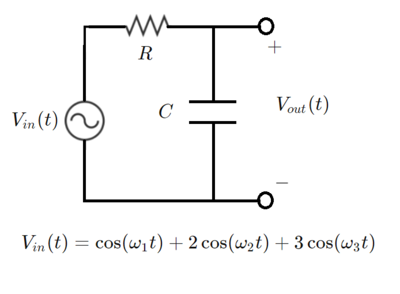
The circuit below is an RC low-pass filter with a voltage input consisting of sinusoids at several different frequencies. The filter cutoff frequency is f c (see details below).
In steady-state, what is the ratio of the RMS output voltage to the RMS input voltage?
Note: This can be solved two different ways. Both methods yield the same result.
- The first way involves a superposition of three different AC steady states - one for each frequency. And then the RMS voltage is the square root of the sum of the squares of the individual voltage magnitudes at each frequency. V R M S = ∣ V ∣ 1 2 + ∣ V ∣ 2 2 + ∣ V ∣ 3 2
- The second way involves a time-domain simulation to calculate the composite capacitor voltage, as well as the calculation of the following integral: V R M S = T 1 ∫ 0 T v 2 ( t ) d t . Note that here, T must be an integer multiple of each of the constituent signal periods.
Details and Assumptions:
- R = 1
- ( f 1 , f 2 , f 3 , f c ) = ( 6 0 , 1 2 0 , 1 8 0 , 9 0 ) .
- ( ω 1 , ω 2 , ω 3 , ω c ) = ( 2 π f 1 , 2 π f 2 , 2 π f 3 , 2 π f c )
- C = R ω c 1

The answer is 0.53.
This section requires Javascript.
You are seeing this because something didn't load right. We suggest you, (a) try
refreshing the page, (b) enabling javascript if it is disabled on your browser and,
finally, (c)
loading the
non-javascript version of this page
. We're sorry about the hassle.
General Outline of Solution
This circuit is analysed in steady-state by applying the principle of superposition.
Consider the voltage component:
V i 1 = cos ( ω 1 t ) The impedance of the circuit considering only this input is:
Z 1 = R + j ω 1 C 1
Here j = − 1 . The current is then:
I 1 = Z 1 V i 1 , m a x
The voltage drop across the capacitor is then:
V o 1 = I 1 ( j ω 1 C 1 )
This same process is repeated for the other two voltage input components which are:
V i 2 = 2 cos ( ω 2 t ) V i 3 = 3 cos ( ω 3 t )
Finally, we obtain output voltages V o 1 , V o 2 , V o 3 , which are complex numbers.
The required answer is then:
A = ∣ V i 1 , m a x ∣ 2 + ∣ V i 2 , m a x ∣ 2 + ∣ V i 3 , m a x ∣ 2 ∣ V o 1 ∣ 2 + ∣ V o 2 ∣ 2 + ∣ V o 3 ∣ 2 = 0 . 5 3
Solution verified by solving the system differential equation numerically and computing the required ratio by evaluating the required integrals, again numerically. A closed-form solution is possible but tedious.