Reactive Power Compensation
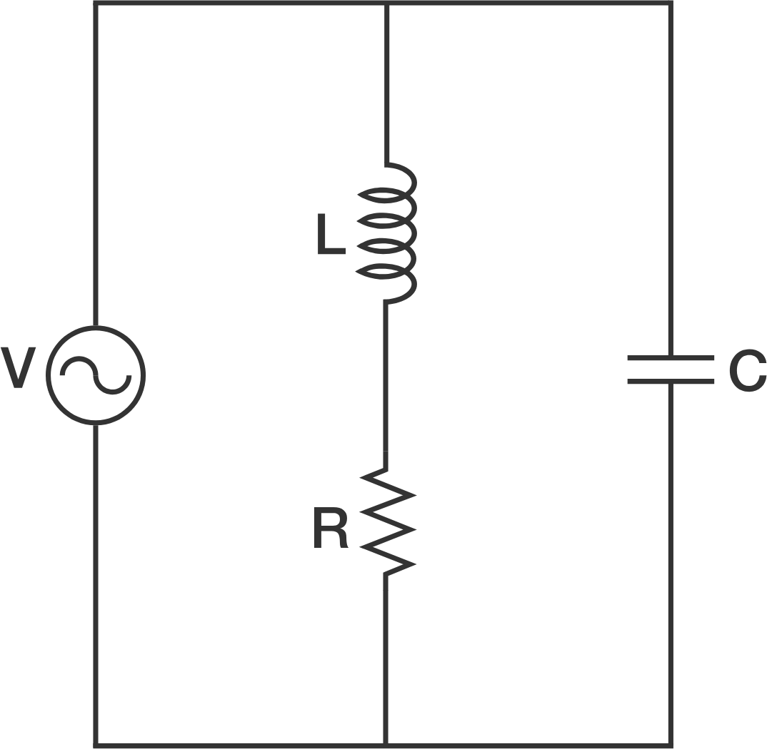
An ideal sinusoidal voltage source is connected across an RLC circuit, as shown above.
The series RL portion represents a load, such as a combination of heating elements and induction motors. The resistance is and the inductive reactance is .
A capacitor is placed in parallel with the load so that the net reactive power consumed by the total RLC combination is zero. Power utilities do this at their substations because they don't want to use up too much of their generation and transmission capability sourcing reactive power that brings in zero revenue.
To 2 decimal places, how many ohms of capacitive reactance are required?
Give your answer as a positive number.
The answer is 6.25.
This section requires Javascript.
You are seeing this because something didn't load right. We suggest you, (a) try
refreshing the page, (b) enabling javascript if it is disabled on your browser and,
finally, (c)
loading the
non-javascript version of this page
. We're sorry about the hassle.
Let the voltage source to have a phase angle of 0, that is V s ∠ 0 = 1 0 ∠ 0 = 1 0 V .
Then the current through the load is I L = Z L V s = 3 + 4 i 1 0 = 2 5 1 0 ( 3 − 4 i ) = 1 . 2 − 1 . 6 i A .
Let the current through the capacitor be I C then the current from the source I s = I L + I C . For the reactive power consumed by the RLC combination to be zero, I s must be in phase with ∣ V s ∣ ∠ 0 or I s = ∣ I s ∣ ∠ 0 . Therefore,
I s ∣ I s ∣ + 0 i ⟹ I C Z C V s Z C 1 0 ⟹ Z C = I L + I C = 1 . 2 − 1 . 6 i + I C = 1 . 6 i = 1 . 6 i = 1 . 6 i = 1 . 6 i 1 0 = − 6 . 2 5 i Ω where Z C is the capacitive reactance.