Resistor ladder; Not as difficult as it looks
Electricity and Magnetism
Level
4
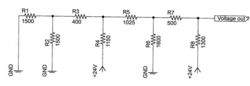 What is the voltage level at the Voltage out point of this circuit?
The answer is 15.
This section requires Javascript.
You are seeing this because something didn't load right. We suggest you, (a) try
refreshing the page, (b) enabling javascript if it is disabled on your browser and,
finally, (c)
loading the
non-javascript version of this page
. We're sorry about the hassle.
Some may have recognized this as an unequal rung R-2R resistor ladder .
This type of arrangement of precision resistors can be used for digital to analog conversion, or DAC. This is a balanced four bit resistor ladder. The digital input is 24 volt high and 0 volt low. The input is entered on the ladder “rungs” at the resistors R2,R4,R6,R8. The input at R8 is the MSB and R2 is the LSB. As the input bits move from MSB to LSB each bit may add a voltage of ½ of the previous bit. This could be calculated by repeatedly using the Thevenin equivalent resistance of the lower significant rungs,
Input value shown as a binary nibble is 1010
MSB---------------------- LSB
E..........D........C..........B
1..........0.........1..........0
24/2 + 0/4 +24/8+0/16 = 15 volts
It would not be necessary to do any detailed calculation once it is established that this is a balance R-2R resistor ladder. That can be confirmed by checking the resistance values across the circuit.
R1 | R2 = 750Ω
R3 in series with R1 | R2 = 400 + 750 = 1150Ω
R4 = 1150 (therefor that rung is balanced)
This calculation can be done or each rung resistor.
As a proof of the validity of the ladder I am posting a detailed calculation of the results.
Thevenin,s theorem can be used repeatedly at points in the circuit to calculating the Thevenin equivalent resistance and the Thevenin equivalent voltage at a point considering only a fraction of the total circuit. More and more resistors, GND and +24 voltage supplies are considered in the circuit until all of the resistors, external power and GND connections are included.
The general principle of the Thevenin theorem is that an electrical network with voltage and current sources and only resistances can be replaced by single power source that is made up of an ideal voltage source in series with an internal resistance. The Thevenin equivalent voltage VthX would be the voltage at the terminal ( X point of interest) when the terminal X is under open circuit condition (no load, no current draw). The Thevenin equivalent resistance RthX which could be considered as the resistance value of an internal resistance in series with the ideal voltage supply to X terminal. In the event that a current is drawn from the terminal there would be a subsequent voltage drop across this internal resistance and therefore the voltage at the terminal will not remain constant The voltage level at virtually every point in the entire circuit will be influenced and change every time a new connection through a resistance to ether the GND or the +24 is added.
Considering the left most connections of the circuit first and working to the right we can beak the circuit into manageable and easily calculated increments to arrive at the answer. In each instance I will consider only the resistors and connection to the left and immediately below the point of interest (terminal). anything to the right of the point of interest is considered not to be connected.
Point F - RthF resistance is through R1|R2 = 1/(1/1500)+1/1500)) = 750 Ω
VthF voltage is 0 volts (both A and B are GND)
Add R3 and R4
Point G – total resistance from F to C = RthF + R3 +R4= 750 +400+1150 = 2300 Ω
(RthF +R3)/2300 = 1150/2300 = .5 (voltage divider from VthF to VC)
VthG = open circuited point G= .5 (VC-VthF) +VthF = .5 (24-0)+0 = 12 volts
RthG = RthF + R3 | R4 = 1/(1/(750+400)+1/(1150)) = 575 Ω
Add R5 and R6
Point H – total resistance from G to D = RthG + R5 +R6= 575 + 1025+1600 = 3200Ω
(RthG +R5)/3200 = (575+1025)/3200 = .5 (voltage divider from VthG to VD)
VthH = open circuited point H=.5 (VE-VthG) +VthG= .5(24- 12) +12 = 6 volts
RthH = Rth + R5 | R6 = 1/(1/(575+1025)+1/(1600)) = 800Ω
Add R7 and R8
Point I – total resistance from H to E = RthH + R7 +R8= 800 + 500 +1300 = 2300Ω
(RthH +R7)/2300 = (800+500)/2300 = .5 (voltage divider from VthH to VE)
VthI = open circuited point I=.5 (VE-VthH) +VthH = .5(24-6) +6 = 15 volts
RthI= RthF + R3 | R4 = 1/(1/(750+400)+1/(1150)) = 575 Ω (not actually required)
Voltage out = 15 volts (this voltage will only hold as long as there is not current draw from the terminal I)