RL 10-14-2020
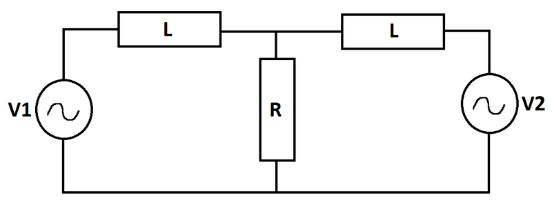
Two voltage sources supply an network as shown. At time , the inductors are de-energized. What is the largest instantaneous value of the current flowing through the resistor?
Bonus: What interesting properties do the inductor currents have?
 Details and Assumptions:
The answer is 1.116.
This section requires Javascript.
You are seeing this because something didn't load right. We suggest you, (a) try
refreshing the page, (b) enabling javascript if it is disabled on your browser and,
finally, (c)
loading the
non-javascript version of this page
. We're sorry about the hassle.
Let the current in the left inductor be I 1 and that through the right inductor be I 2 . The circuit equations read:
L I ˙ 1 + R ( I 1 + I 2 ) = V 1 L I ˙ 2 + R ( I 1 + I 2 ) = V 2
Adding the above equations:
L ( I ˙ 1 + I ˙ 2 ) + 2 R ( I 1 + I 2 ) = V 1 + V 2
Let ω = 2 π . Here, I = I 1 + I 2 is the resistor current. It can also be seen that I ( 0 ) = 0 . The final differential equation for resistor current is:
L I ˙ + 2 I R = V 1 + V 2
The above equation has a null solution and a particular solution. The null and particular solutions are:
I n = I o e − 2 t / 3 I p = 9 ω 2 + 4 1 0 ( 2 + 3 ω ) sin ( ω t ) + 1 0 ( 2 − 3 ω ) cos ( ω t )
Adding up both solutions and solving for I o gives:
I ( t ) = 9 ω 2 + 4 1 0 ( 2 + 3 ω ) sin ( ω t ) + 1 0 ( 2 − 3 ω ) cos ( ω t ) − 9 ω 2 + 4 1 0 ( 2 − 3 ω ) e − 2 t / 3
The steps for solving have been left out. I used the D operator method to solve this equation. Other techniques such as the method of integrating factors, or Laplace transformation will work just as well here. Plotting the above function:
The inductor currents can be solved for by integrating the following equations:
I 1 = ∫ 0 t L V 1 ( τ ) − R I ( τ ) d τ I 2 = ∫ 0 t L V 2 ( τ ) − R I ( τ ) d τ
I do not observe anything unexpected. The currents are a little higher initially due to the presence of the decaying exponential which goes away with time. A phase difference in the steady state solution between inductor currents is also not unexpected. I think I am unable to latch onto any interesting behaviour at the moment.