RLC (4-24-2021)
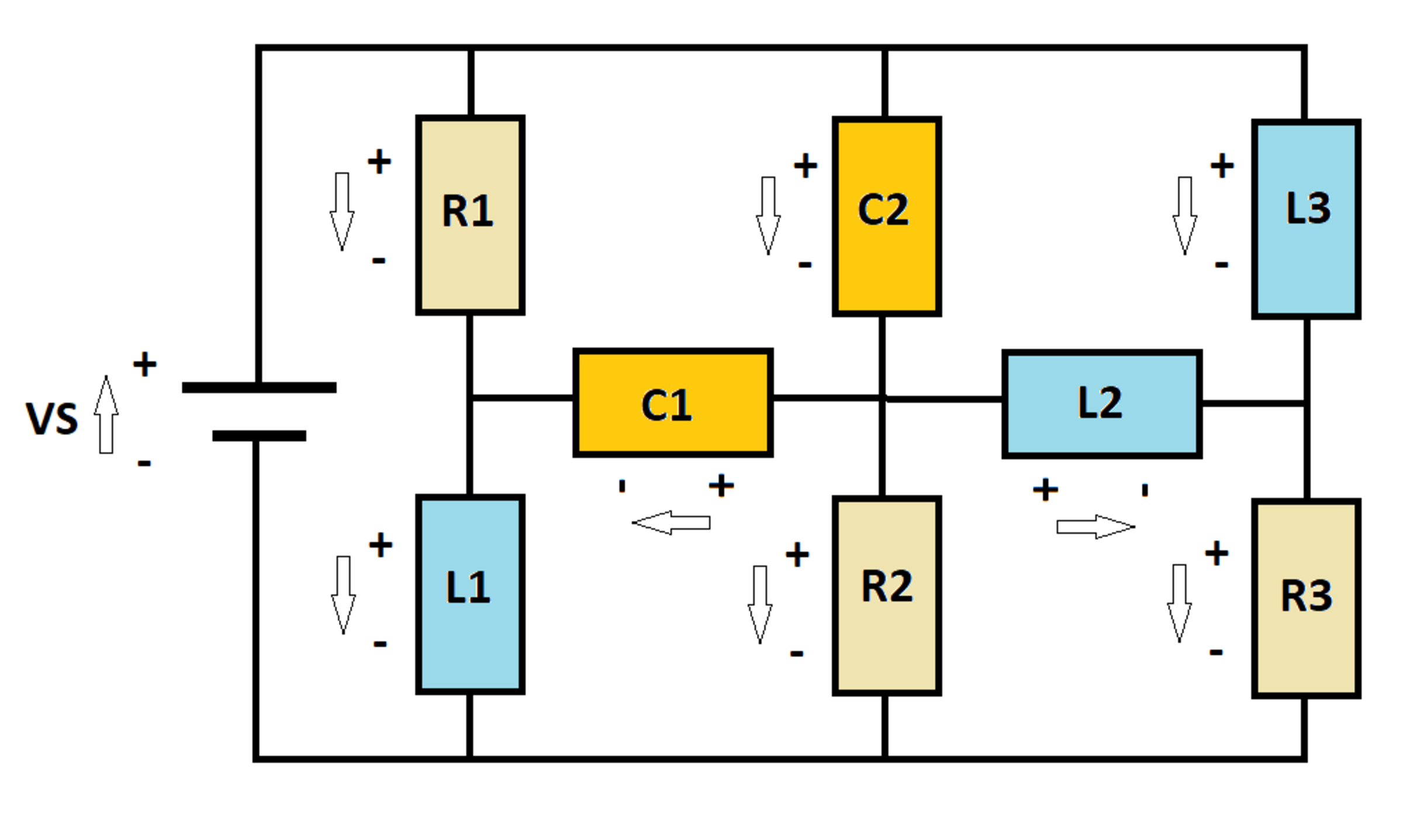
A D C voltage source V S excites an R L C circuit as shown. At time t = 0 , the inductors and capacitors are de-energized. Let I S ( t ) be the current flowing out of the source.
Let I S 0 and I S ∞ be the values of I S ( t ) at t = 0 and t = ∞ , respectively. Let I S M be the maximum value of I S ( t ) between t = 0 and t = ∞ .
Determine the following ratio:
I S 0 + I S ∞ I S M
Details and Assumptions:
1)
V
S
=
1
0
volts
2)
R
1
=
R
2
=
R
3
=
1
Ω
3)
L
1
=
L
2
=
L
3
=
1
H
4)
C
1
=
C
2
=
5
F
5)
I have included polarity markers for the current (arrows) and for the voltage (plus/minus signs).

The answer is 0.908.
This section requires Javascript.
You are seeing this because something didn't load right. We suggest you, (a) try
refreshing the page, (b) enabling javascript if it is disabled on your browser and,
finally, (c)
loading the
non-javascript version of this page
. We're sorry about the hassle.
2 solutions
@Steven Chase
After 2-3month if I will make my own app for posting science problem , how I will tell you the name of app?
This is the best opportunity to make app . Right?
We should not depend on Brilliant ,
We should be Self Dependent. I will invite Karan Chatrath also in that app
The circuit equations as per Kirchoff's current and voltage laws are:
I C 1 + I R 1 = I L 1 … ( 1 ) I C 2 = I C 1 + I L 2 + I R 2 … ( 2 ) I R 3 = I L 3 + I L 2 … ( 3 ) I S = I R 1 + I C 2 + I L 3 … ( 4 ) I ˙ L 1 = V S − I R 1 … ( 5 ) Q ˙ C 1 = I C 1 … ( 6 ) Q ˙ C 2 = I C 2 … ( 7 ) I ˙ L 2 = I R 2 − I R 3 … ( 8 ) I R 1 = 5 Q C 1 + Q C 2 … ( 9 ) Q C 1 + I ˙ L 1 = I R 2 … ( 1 0 ) I ˙ L 3 − I ˙ L 2 − 5 Q C 2 = 0 … ( 1 1 )
Initial conditions:
I L 1 ( 0 ) = I L 2 ( 0 ) = I L 3 ( 0 ) = Q C 1 ( 0 ) = Q C 2 ( 0 ) = 0
By inspecting the circuit, one can easily conclude that at t = 0 the source current I S = 1 0 A and at steady state I S = 3 0 A . These results are found using the initial conditions.
A plot of source current as a function of time is as follows:
This is a 5th order circuit. Instead of simplifying the expressions, I have chosen a purely numerical approach:
1 2 3 4 5 6 7 8 9 10 11 12 13 14 15 16 17 18 19 20 21 22 23 24 25 26 27 28 29 30 31 32 33 34 35 36 37 38 39 40 41 42 43 44 45 46 47 48 49 50 51 52 53 54 55 |
|
I will post my solution as well, which is the same as that of @Karan Chatrath, apart from minor stylistic differences. The key here is to write the time derivatives of the state variables in terms of the state variables and the forcing function (that is known as a state-space formulation). The state variables are the inductor currents and the capacitor voltages, and the forcing function is the DC source. Calculating the time derivatives allows for numerical integration.