RLC 6-17-2020
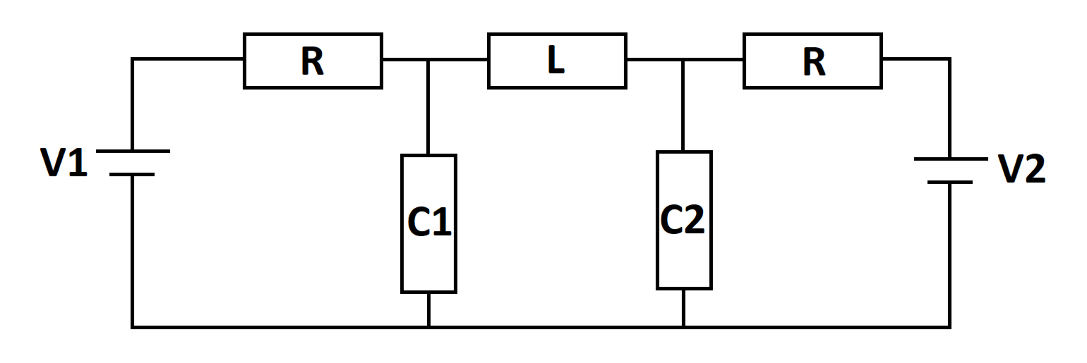
An RLC circuit is excited by two DC voltage sources. At time , the capacitors and inductors are de-energized. Let be the maximum value of the voltage across capacitor over all time. Let be the limiting value of the voltage across capacitor as the elapsed time approaches infinity.
What is ?
Details and Assumptions:
1)
2)
3)
4)
The answer is 1.194.
This section requires Javascript.
You are seeing this because something didn't load right. We suggest you, (a) try
refreshing the page, (b) enabling javascript if it is disabled on your browser and,
finally, (c)
loading the
non-javascript version of this page
. We're sorry about the hassle.
Charge on C 1 : Q 1
Charge on C 2 : Q 2
Source current through V 1 : I V 1
Source current through V 2 : I V 2
Initial conditions:
Q 1 ( 0 ) = Q 2 ( 0 ) = I L ( 0 ) = 0
Circuit Equations:
I V 1 = I L + I C 1 I C 2 = I L + I V 2 Q ˙ 1 = I C 1 Q ˙ 1 = I C 2 − V 1 + R I V 1 + C 1 Q 1 = 0 − V 2 + R I V 2 + C 2 Q 2 = 0 L I ˙ L + C 2 Q 2 = C 1 Q 1
Laplace Transform on both sides:
I V 1 ( s ) = I L ( s ) + I C 1 ( s ) I C 2 ( s ) = I L ( s ) + I V 2 ( s ) s Q 1 ( s ) = I C 1 ( s ) s Q 2 ( s ) = I C 2 ( s ) − s V 1 + R I V 1 ( s ) + C 1 Q 1 ( s ) = 0 − s V 1 + R I V 2 ( s ) + C 2 Q 2 ( s ) = 0 L s I L + C 2 Q 2 ( s ) = C 1 Q 1 ( s )
Plugging in parameters and solving for Q 1 ( s ) :
Q 1 ( s ) = s ( s + 1 0 ) ( s 2 + 1 0 s + 2 0 ) 2 0 ( s 2 + 1 0 s + 1 5 )
Therefore voltage across capacitor C 1 :
V C 1 ( s ) = C 1 Q 1 ( s ) = s ( s + 1 0 ) ( s 2 + 1 0 s + 2 0 ) 2 0 0 ( s 2 + 1 0 s + 1 5 )
Using an online inverse Laplace transform calculator and re-arranging the result a little, gives:
V C 1 ( t ) = 1 0 5 e − 5 t s i n h ( 5 t ) − 1 5 e − 1 0 t + 1 5
Variation of V C 1 with time: