RLC DC Transient (Part 2)
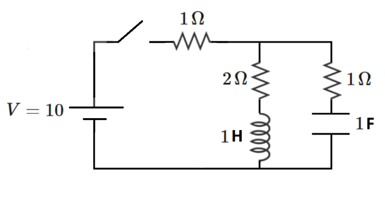
The RLC circuit below is excited by a DC voltage source through a switch which is initially open. Prior to switch closing, the inductor and the capacitor are de-energized.
The switch closes at time t = 0 . Let I S ( t ) be the current flowing out of the voltage source, and let I S ∞ be the current flowing out of the voltage source as the elapsed time approaches infinity (representing DC steady-state).
Determine the following integral:
Q = ∫ 0 4 ( I S ( t ) − I S ∞ ) d t
Give your answer as ⌊ 1 0 0 0 Q ⌋ , where ⌊ ⋅ ⌋ denotes the floor function.
Note: Relative to the previous problem, a resistor has been added, and the time window for the integral has changed
The answer is 3048.
This section requires Javascript.
You are seeing this because something didn't load right. We suggest you, (a) try
refreshing the page, (b) enabling javascript if it is disabled on your browser and,
finally, (c)
loading the
non-javascript version of this page
. We're sorry about the hassle.
2 solutions
I got the value of the integral as 3.048966, but missed the last requirement. Current through the voltage source is given by I=(10/3)-(5/6)(√3-1)exp(-(3+√3)/2)+(5/6)(√3+1)exp(-(3-√3)/2). The steady state current is (10/3). Integrating within the given limits, I got the result.
@Josh Silverman I can't see who has solved this problem, even though it says there are solvers. Is this some sort of bug?
Log in to reply
Interesting. I'll look into this.
Log in to reply
Thanks for checking
It looks like the Latex isn't displaying consistently now either (in general)
Hi Josh. A few more bugs to report. Thanks in advance. By the way, any word on the "hidden solvers" issue?
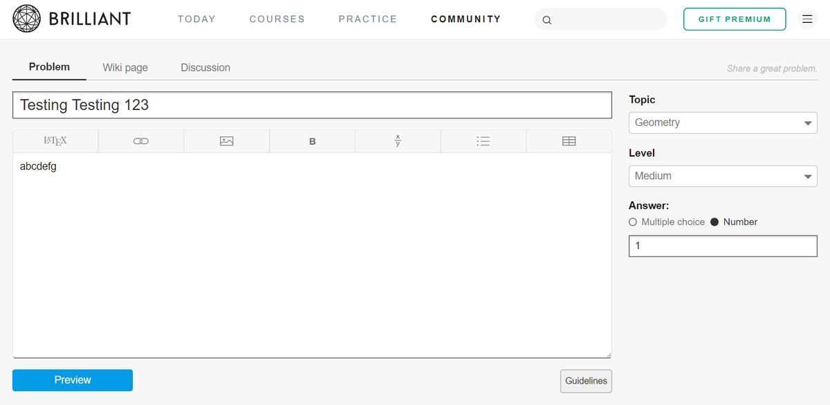
1) Major - The site seems to be deciding the answers to my community problems for me. This has been broken in my Chrome browser for months, so I've been using Microsoft Edge just to post problems. Now it's broken in Edge too. Below are screenshots of (1): initial problem formulation with user-defined answer, (2) first preview (good so far), (3) going back to the problem creation page (result now broken), (4) previewing again (result still broken). I effectively can't post problems from my home machine now.
2) Minor - It appears that large-formatted Latex no longer properly displays things on separate lines. Many of my problems which used to display fine (and solutions too) are now broken. See example below. It displays fine again if the large formatting is removed. This is a minor thing, but it is new behavior.
https://brilliant.org/problems/paraboloid-constrained-maxdist/?ref_id=1570603
Screenshots for bug #1:


The hidden solvers issue is in the bug queue now. Can you send me some screenshots of the TeX problems?
Log in to reply
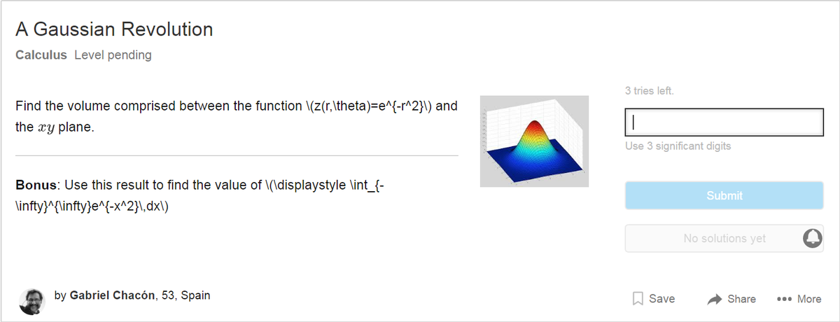
One interesting piece of data. When I solved the "Gaussian Revolution" problem, the display immediately started working. And then after leaving and coming back, the display is bad again
Good to hear. Here is a specific example of the Latex thing, but I've seen it many places.
We are going to use s-domain analysis and Laplace transformation. (Roughly speaking, s corresponds to j ω , where j = − 1 .) The impedance of the circuit is Z = 1 + 3 + s + 1 / s ( 2 + s ) ( 1 + 1 / s ) . The admittance is Y = 1 / Z . The Laplace transform of the unit step function is 1 / s ; for a 10V source it is 1 0 / s . The time dependent current is the inverse Laplace transform of
s 1 0 Y = s ( 1 + 3 + s + 1 / s ( 2 + s ) ( 1 + 1 / s ) ) 1 0
Feeding this function to an inverse Laplace transformator (e.g. here ) we get
i ( t ) = 1 0 [ 3 1 + 1 2 3 + 1 e − α t − 1 2 3 − 1 e − β t ]
where α = 2 3 − 3 and β = 2 3 + 3
Feeding i ( t ) − 3 1 0 to an integral calculator (like this ) yields Q = 3 . 0 4 8 9 7
It isn't really necessary to have a closed form solution, so I won't bother deriving one. Instead, I will employ a very useful concept; that of the "state space". The "state space" formulation expresses the time-derivatives of the things you want to solve for, in terms of the present values of the things you want to solve for (and any forcing functions). That is useful because knowing the rate of change allows us to predict the state a very short time later. The system dynamics can thus be simulated in small, sequential, steps.
x ˙ = f ( x , u )
In the above equation, x represents a state variable to be solved for (like the voltage across a capacitor or the current through an inductor). The quantity u is the system forcing function (the voltage source, for example). Below is a more general representation of the circuit for t ≥ 0 .
Let the current and voltage for the inductor be I L , V L , and let the current and voltage for the capacitor be I C , V C . I L and V C are the state variables that we solve for. Note that in circuit analysis, the state variables are associated with energy storage. The fundamental equations are:
V L = L I L ˙ I C = C V C ˙
The right-hand sides already resemble one side of the state-space equation. But we need to get the left-hand sides expressed in terms of state variables I L and V C . Start by writing an expression for the source current.
I S = I L + I C I S = I L + R 2 V S − R S I S − V C
Re-arranging gives:
I S = 1 + R S / R 2 I L + V S / R 2 − V C / R 2
Now we can write the state-space equation for the inductor current (recall that I S contains both state variables):
V L = L I L ˙ V S − R S I S − R 1 I L = L I L ˙ I L ˙ = L V S − R S I S − R 1 I L
And for the capacitor voltage (recall that I S contains both state variables):
I C = C V C ˙ I S − I L = C V C ˙ V C ˙ = C I S − I L
Numerically integrating the derivatives (from appropriate starting conditions) results in the following plot. I have plotted all the way to t = 1 0 for illustration purposes. By inspection, we know that the source current should start at 5 and approach 3 1 0 as time goes to infinity. The plot shows this behavior. The desired integral can be included as part of the simulation.