RLC Switching - Quantitative

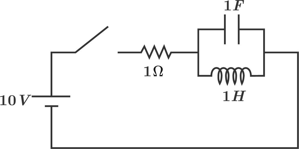
In the circuit below (with DC source), the switch closes at t = 0. t = 0. Prior to closing, the inductor and capacitor are completely de-energized. What is the value of the ratio Maximum resistor current for t 0 Minimum resistor current for t 0 ? \frac{\text{Maximum resistor current for} \, t \geq 0}{\text{Minimum resistor current for} \, t \geq 0}\, \large ?


The answer is 2.4.

This section requires Javascript.
You are seeing this because something didn't load right. We suggest you, (a) try refreshing the page, (b) enabling javascript if it is disabled on your browser and, finally, (c) loading the non-javascript version of this page . We're sorry about the hassle.

2 solutions

We can use Laplace transform to solve this. After taking the transform to the circuit, we get:

  • The source is V ( s ) = 10 s V(s)=\dfrac{10}{s} .
  • The impedance of the resistor is R = 1 R=1 .
  • The impedance of the capacitor is X C = 1 s X_C=\dfrac{1}{s} .
  • The impedance of the inductor is X L = s X_L=s .

Then we have I R ( s ) = V ( s ) R + X C X L X C + X L = 10 ( s 2 + 1 ) s ( s 2 + s + 1 ) I_R(s) = \dfrac{V(s)}{R + \dfrac{X_C X_L}{X_C + X_L}} = \dfrac{10(s^2+1)}{s(s^2+s+1)} .

We propose the following partial fraction descomposition: I R ( s ) = A s + z s z 1 + z s z 2 I_R(s) = \dfrac{A}{s} + \dfrac{z}{s-z_1} + \dfrac{\overline{z}}{s-z_2} , where z 1 , 2 = 1 2 ± 3 2 i z_{1,2}=-\dfrac{1}{2} \pm \dfrac{\sqrt{3}}{2}i are the roots of s 2 + s + 1 = 0 s^2+s+1=0 .

Hence we have: A = I R ( s ) ( s 0 ) s = 0 = 10 A=I_R(s)(s-0) |_{s=0}=10 and z = I R ( s ) ( s z 1 ) s = z 1 = 10 3 i z=I_R(s)(s-z_1) |_{s=z_1}=\dfrac{10}{\sqrt{3}}i .

Take inverse Laplace transform: i R ( t ) = A + z e z 1 t + z e z 2 t = 10 + 10 3 i e ( 1 2 + 3 2 i ) t 10 3 i e ( 1 2 3 2 i ) t = 10 20 3 e t 2 sin ( 3 2 t ) i_R(t) = A + ze^{z_1 t} + \overline{z}e^{z_2 t} = 10 + \dfrac{10}{\sqrt{3}}ie^{\left( -\frac{1}{2}+\frac{\sqrt{3}}{2}i \right)t} - \dfrac{10}{\sqrt{3}}ie^{\left( -\frac{1}{2}-\frac{\sqrt{3}}{2}i \right)t} = 10 - \dfrac{20}{\sqrt{3}} e^{-\frac{t}{2}} \sin\left(\dfrac{\sqrt{3}}{2}t\right) .

Now, i R ( t ) = 20 3 e t 2 ( 1 2 sin ( 3 2 t ) + 3 2 cos ( 3 2 t ) ) i_R'(t) = -\dfrac{20}{\sqrt{3}} e^{-\frac{t}{2}}\left( -\dfrac{1}{2}\sin\left(\dfrac{\sqrt{3}}{2}t\right) + \dfrac{\sqrt{3}}{2} \cos\left(\dfrac{\sqrt{3}}{2}t\right) \right) . The minimum value will occur at the first positive solution of i R ( t ) = 0 i_R'(t)=0 and the maximum value at the second.

So, i R ( t ) = 0 1 2 sin ( 3 2 t ) = 3 2 cos ( 3 2 t ) tan ( 3 2 t ) = 3 t = 2 3 ( π 3 + π k ) i_R'(t) = 0 \implies \dfrac{1}{2}\sin\left(\dfrac{\sqrt{3}}{2}t\right) = \dfrac{\sqrt{3}}{2} \cos\left(\dfrac{\sqrt{3}}{2}t\right) \implies \tan\left(\dfrac{\sqrt{3}}{2}t\right) = \sqrt{3} \implies t = \dfrac{2}{\sqrt{3}}\left(\dfrac{\pi}{3} + \pi k\right) .

Finally:

  • The minimum current will occur at t m i n = 2 π 3 3 t_{min}=\dfrac{2\pi}{3\sqrt{3}} with value i R ( t m i n ) = 10 ( 1 e π 3 3 ) i_R(t_{min})=10\left(1-e^{-\frac{\pi}{3\sqrt{3}}}\right) .
  • The maximum current will occur at t m a x = 8 π 3 3 t_{max}=\dfrac{8\pi}{3\sqrt{3}} with value i R ( t m a x ) = 10 ( 1 + e 4 π 3 3 ) i_R(t_{max})=10\left(1+e^{-\frac{4\pi}{3\sqrt{3}}}\right) .
  • The ratio is i R ( t m a x ) i R ( t m i n ) = 1 e π 3 3 1 + e 4 π 3 3 2.4003 \dfrac{i_R(t_{max})}{i_R(t_{min})}=\dfrac{1-e^{-\frac{\pi}{3\sqrt{3}}}}{1+e^{-\frac{4\pi}{3\sqrt{3}}}} \approx \boxed{2.4003} .

Well done!

Steven Chase - 3 years, 4 months ago
Steven Chase
Jan 18, 2018

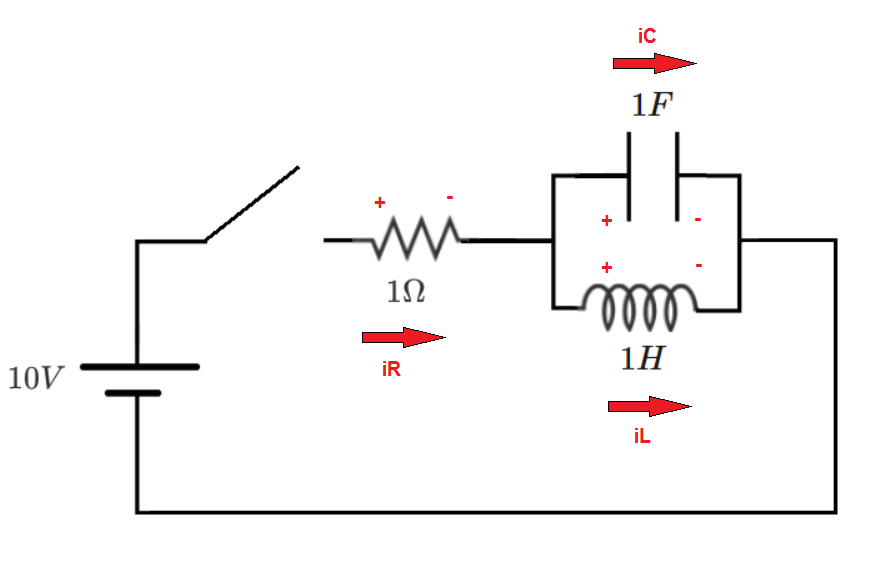
The system state variables are the capacitor voltage and the inductor current. Write expressions for the time-derivatives of the state variables in terms of the state variables and the forcing function (the DC source voltage). Note the voltage and current polarity conventions in the diagram.

Capacitor:

i C = C d v C d t i R i L = C d v C d t v S v C R i L = C d v C d t d v C d t = v S v C R i L C \large{i_C = C \frac{dv_C}{dt} \\ i_R - i_L = C \frac{dv_C}{dt} \\ \frac{v_S - v_C}{R} - i_L = C \frac{dv_C}{dt} \\ \frac{dv_C}{dt} = \frac{\frac{v_S - v_C}{R} - i_L}{C}}

Inductor:

v L = L d i L d t v C = L d i L d t d i L d t = v C L \large{v_L = L \frac{d i_L}{dt} \\ v_C = L \frac{d i_L}{dt} \\ \frac{d i_L}{dt} = \frac{v_C}{L}}

Numerical integration yields a minimum resistor current value of 4.537, and a maximum value of 10.891, with the ratio of the two being approximately 2.4. The current reaches a constant value of 10 amps in steady-state, as expected.

0 pending reports

×

Problem Loading...

Note Loading...

Set Loading...