RLC Transient (3-1-2020)
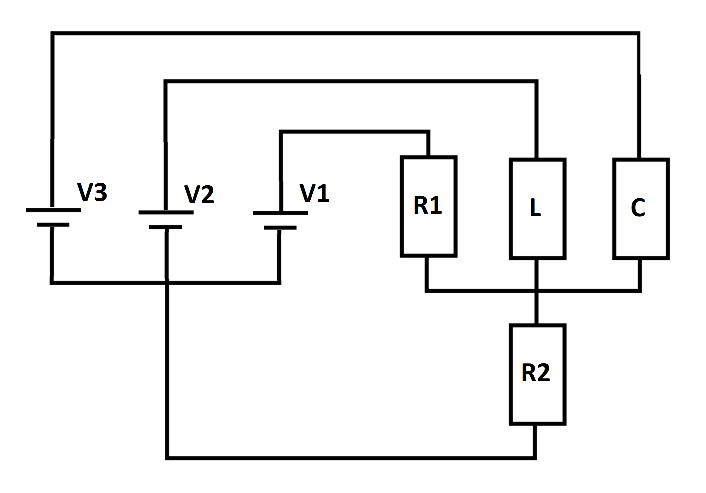
Three DC voltage sources energize an RLC network, as shown below. At time , the inductor and capacitor are de-energized. Let be the current flowing in resistor at time . Let be the limiting value of the current flowing in resistor as the elapsed time approaches infinity. Let be the smallest value of current flowing in resistor over all time. Let be the largest value of the current flowing in for .
Determine the following ratio:
Details and Assumptions:
1)
2)
3)
4)
5)
6)
7)
8)
All four currents are positive numbers

The answer is 0.693.
This section requires Javascript.
You are seeing this because something didn't load right. We suggest you, (a) try
refreshing the page, (b) enabling javascript if it is disabled on your browser and,
finally, (c)
loading the
non-javascript version of this page
. We're sorry about the hassle.
The state variables are the inductor I L current and the capacitor voltage I C . Let the voltage across R 2 be V R 2 . The state-space model is:
V R 2 = V 3 − V C I R 1 = R 1 V 1 − V R 2 I R 2 = R 2 V R 2 V L = V 2 − V R 2 = L I ˙ L I C = I R 2 − I R 1 − I L = C V ˙ C
Numerical integration results in the following plot of I R 2 . At time t = 0 , the capacitor voltage is zero, meaning that V 3 appears across R 2 , resulting in 2 3 0 = 1 5 units of current. At t = ∞ , the inductor is a short circuit, meaning that V 2 appears across R 2 , resulting in 2 2 0 = 1 0 units of current. Since the circuit has both capacitance and inductance, there is an intermediate transient with damped oscillation.