RLC with Nonlinear Resistor
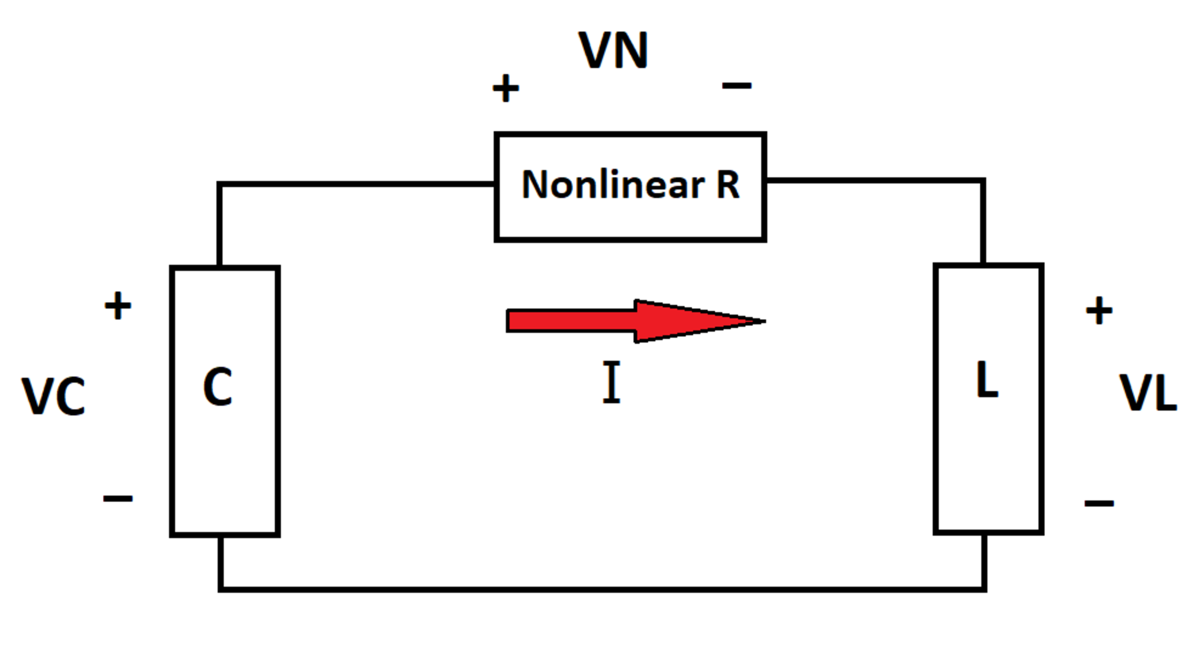
Consider a circuit containing a capacitor, an inductor, and a nonlinear resistor. The voltage across the nonlinear resistor is V N , and the current through it is I . The relationship between incremental V N and incremental I is given by:
d I d V N = R 0 e − α V N
At time t = 0 , V N = I = 0 and the capacitor voltage V C = 1 0 . At time t = 1 0 , what is the instantaneous power dissipated by the nonlinear resistor?
Bonus: Do the various physical aspects of the circuit's behavior make sense?
Details and Assumptions:
1)
α
=
1
2)
R
0
=
2
3)
L
=
C
=
1
4)
All quantities are in the appropriate standard
S
I
units
5)
The quantity
e
is Euler's number
The answer is 0.768.
This section requires Javascript.
You are seeing this because something didn't load right. We suggest you, (a) try
refreshing the page, (b) enabling javascript if it is disabled on your browser and,
finally, (c)
loading the
non-javascript version of this page
. We're sorry about the hassle.
2 solutions
With the initial conditions V N = 0 at I = 0 we solve the differential equation for the non-linear resistor: R 0 = V N ( 1 ) ( I ) e α V N ( I ) = α 1 ⋅ d I d e α V N ( I ) ⇒ R 0 ( I − 0 ) = α 1 [ e α V N ( I ) − e 0 ] ∣ ∣ ∣ ∣ ∣ ∣ ∣ I → I ′ ∫ 0 I … d I ′ We solve for I to notice the non-linear resistor is in fact a diode, because it has the equation of a diode: I = α R 0 1 ( e α V N ( I ) − 1 ) ⇒ V N ( I ) = α 1 lo g ( α R 0 I + 1 ) = lo g ( 2 I + 1 ) Let the state vector be x ( t ) = ( V C , I ) T ( t ) . Then we can use KCL for the first equation and KVL for the second equation of the state space system: ( C V C ( 1 ) ( t ) L I ( 1 ) ( t ) ) = ( − I ( t ) V C ( t ) − V N ( I ) ) C = L = 1 ⇒ x ( 1 ) ( t ) = ( − I ( t ) V C ( t ) − lo g ( 2 I ( t ) + 1 ) ) = : f ( x ( t ) ) , x ( 0 ) = ( 1 0 0 ) We have to solve this non-linear system of equation numerically (see below) and get P ( 1 0 ) ≈ 0 . 7 6 8 .
/* maxima program to find P(10) */
/* define state space system */
ode : [
    -i,                 /* = d/dt vc(t) */
    vc - log(2 * i + 1) /* = d/dt i(t) */
]$

/* solve ode numerically via 4th order runge-kutta */
result : rk(ode,
    [vc, i],            /* state vector */
    [10, 0],            /* initial conditions */
    ['t, 0, 10, 1e-2]   /* t in [0; 10] with step-size 1e-2 */
)$

/* calculate power VN * I at t = 10 (result colums: [t, vc, i]) */
P : log(2 * last(result)[3] + 1) * last(result)[3];
Rem.:
Let's take a look at
V
C
(
t
)
and
I
(
t
)
:
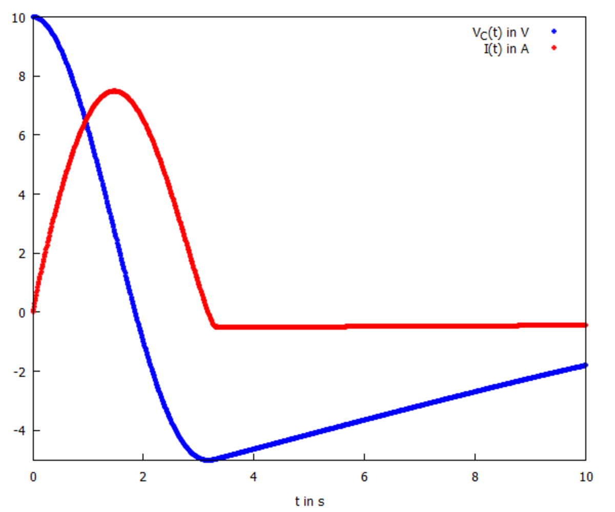 Let's try to make sense of what we see: For
0
≤
t
≤
3
.
1
, the current is positive, so the diode let's the current through and acts similar to a small resistor. As a result, both current and voltage look similar to the cosine and sine we would expect of the ideal LC-circuit without the diode.
Let's try to make sense of what we see: For
0
≤
t
≤
3
.
1
, the current is positive, so the diode let's the current through and acts similar to a small resistor. As a result, both current and voltage look similar to the cosine and sine we would expect of the ideal LC-circuit without the diode.
For t > 3 . 1 , the current changes its sign and the diode starts blocking the current: It acts similar to a large resistor! As a result, the voltage looks like a slowly decaying exponential - exactly what we would expect of a series RCL-circuit with a large resistor! The same is true for the current, but it is too small to see in the graph above.
The circuit equations are:
− C Q + V N + L I ˙ = 0 − Q ˙ = I V ˙ N = R o e − α V N I ˙ V N ( 0 ) = I ( 0 ) = 0 ; Q ( 0 ) = 1 0
Q is the instantaneous charge on the capacitor and I is the current flowing in the circuit. Now, numerical integration does the rest. A plot for the cases α = 1 and α = 0 are shown below. For the case α = 0 , one can see that V N is twice the value of I at all instants of time. This is the linear behaviour of Ohm's law. For the case α = 1 , this is clearly not the case. Moreover, when α = 1 , the capacitor discharges to a point of opposite electric polarity and then again discharges from that instant to zero.