RLC Y Circuit (Part 2)

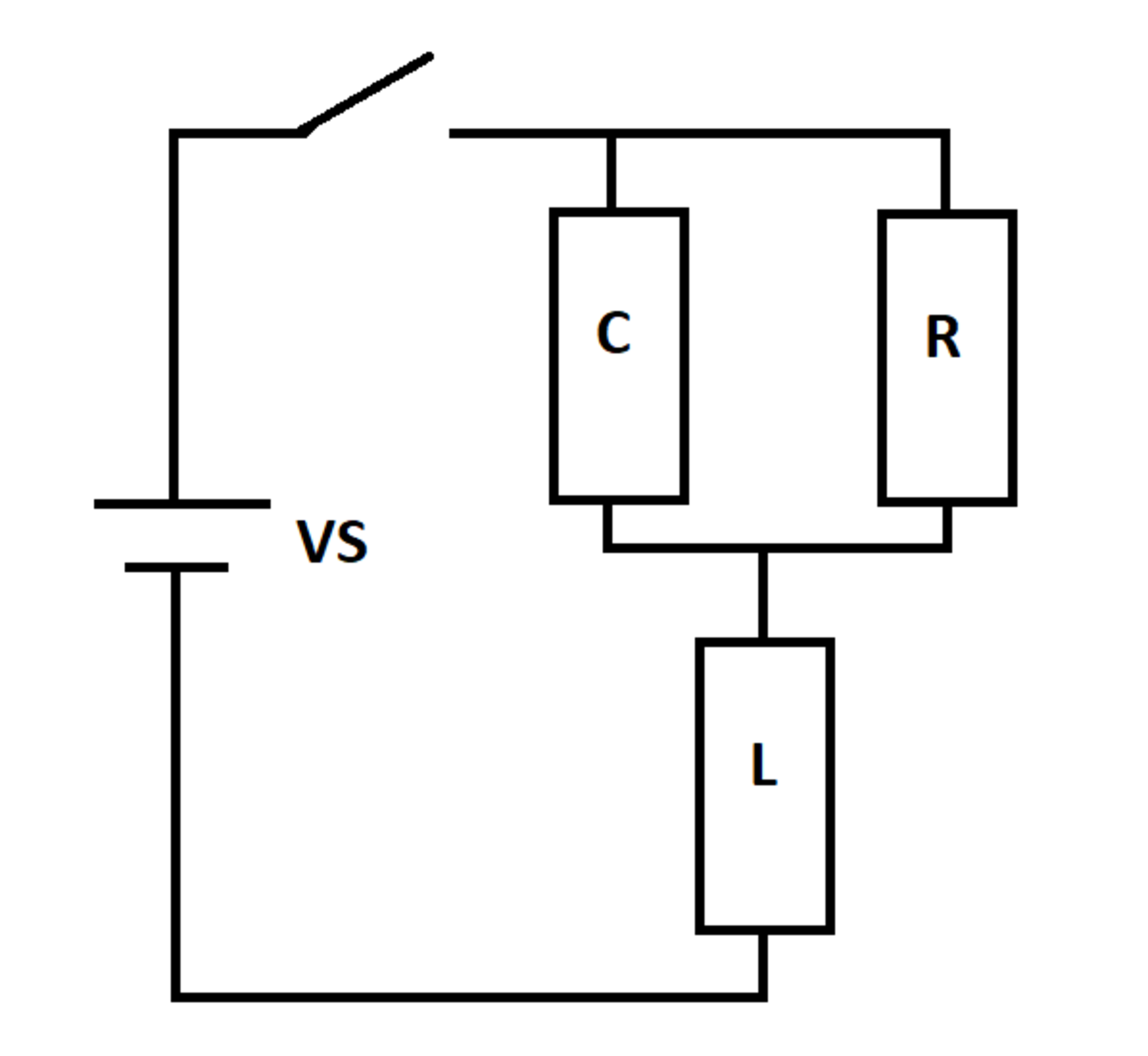
An RLC circuit is excited by a DC voltage source. The switch closes at time t = 0 t = 0 , at which time the inductor and capacitor are de-energized.

Let I m i n I_{min} and I m a x I_{max} be the smallest and largest source current values for t > 2 t > 2 . Let I 0 + I_{0+} be the source current right after the switch closes, and let I I_{\infty} be the steady-state source current as the elapsed time approaches infinity.

Determine the following ratio:

I m i n + I m a x I 0 + + I \large{\frac{I_{min} + I_{max}}{I_{0+} + I_{\infty}}}

Details and Assumptions:
1) There are no negative numbers in the ratio
2) R = L = C = 1 R = L = C = 1
3) V S = 10 V_S = 10
4) The circuit topology has changed relative to the previous problem


The answer is 2.2498.

This section requires Javascript.
You are seeing this because something didn't load right. We suggest you, (a) try refreshing the page, (b) enabling javascript if it is disabled on your browser and, finally, (c) loading the non-javascript version of this page . We're sorry about the hassle.

1 solution

Karan Chatrath
Dec 1, 2019

The circuit equations based on Kirchoff's laws are as follows. I R I_R is the current through the resistor, I C I_C is that through the capacitor and I L I_L is that through the inductor. The charge on the capacitor is Q Q .

I R R + L d I L d t = V S I_RR + L\frac{dI_L}{dt} = V_S I R R = Q C I_RR = \frac{Q}{C} I L = I R + I C I_L = I_R + I_C I C = d Q d t I_C = \frac{dQ}{dt}

At t = 0 t = 0 the charge on the capacitor and all currents are zero.

By manipulating the above equations, we get:

d I R d t + d I R d t = I R + V S \frac{dI_R}{dt} + \frac{dI_R}{dt} = -I_R + V_S d I R d t = I C \frac{dI_R}{dt} = I_C

Now this can be rearranged as:

[ 1 1 1 0 ] [ I ˙ R I ˙ C ] = [ 1 0 0 1 ] [ I R I C ] + [ 1 0 ] V S \left[\begin{matrix}1&1\\1&0\end{matrix}\right]\left[\begin{matrix}\dot{I}_R\\\dot{I}_C\end{matrix}\right] = \left[\begin{matrix}-1&0\\0&1\end{matrix}\right]\left[\begin{matrix}I_R\\I_C\end{matrix}\right] + \left[\begin{matrix}1\\0\end{matrix}\right]V_S

Which implies:

[ I ˙ R I ˙ C ] = [ 1 1 1 0 ] 1 [ 1 0 0 1 ] [ I R I C ] + [ 1 1 1 0 ] 1 [ 1 0 ] V S \left[\begin{matrix}\dot{I}_R\\\dot{I}_C\end{matrix}\right] =\left[\begin{matrix}1&1\\1&0\end{matrix}\right]^{-1}\left[\begin{matrix}-1&0\\0&1\end{matrix}\right]\left[\begin{matrix}I_R\\I_C\end{matrix}\right] + \left[\begin{matrix}1&1\\1&0\end{matrix}\right]^{-1} \left[\begin{matrix}1\\0\end{matrix}\right]V_S

Also:

I L = [ 1 1 ] [ I R I C ] I_L = \left[\begin{matrix}1&1\end{matrix}\right]\left[\begin{matrix}I_R\\I_C\end{matrix}\right]

Using shorthand notation:

x ˙ = A x + B u ; I L = C x \boxed{\dot{x} = Ax + Bu \ ; \ I_L = Cx} Where: A = [ 1 1 1 0 ] 1 [ 1 0 0 1 ] A = \left[\begin{matrix}1&1\\1&0\end{matrix}\right]^{-1}\left[\begin{matrix}-1&0\\0&1\end{matrix}\right] B = [ 1 1 1 0 ] 1 [ 1 0 ] B = \left[\begin{matrix}1&1\\1&0\end{matrix}\right]^{-1} \left[\begin{matrix}1\\0\end{matrix}\right] C = [ 1 1 ] C = \left[\begin{matrix}1&1\end{matrix}\right] x = [ I R I C ] x = \left[\begin{matrix}I_R\\I_C\end{matrix}\right]

Now, numerical integration does the rest. This can also be solved analytically. A plot of I L I_L vs. Time is:

From here, the required answer is computed which comes out to be approximately 2.25 \boxed{2.25} .

Nice problem. I suggest a third version of this problem with the resistor and inductor in parallel, in combination with the capacitor in series, would complete this 'Y-circuit' problem set.

Karan Chatrath - 1 year, 6 months ago

Log in to reply

Thanks for the solution. I will post "Part 3" as well. I find these little circuit transient problems to be rather addictive

Steven Chase - 1 year, 6 months ago

Log in to reply

I enjoy these problems too. Thanks for sharing. It would be fun to analyze these circuits in the frequency domain. But I think that's already covered in the domain of AC circuits.

Karan Chatrath - 1 year, 6 months ago

0 pending reports

×

Problem Loading...

Note Loading...

Set Loading...