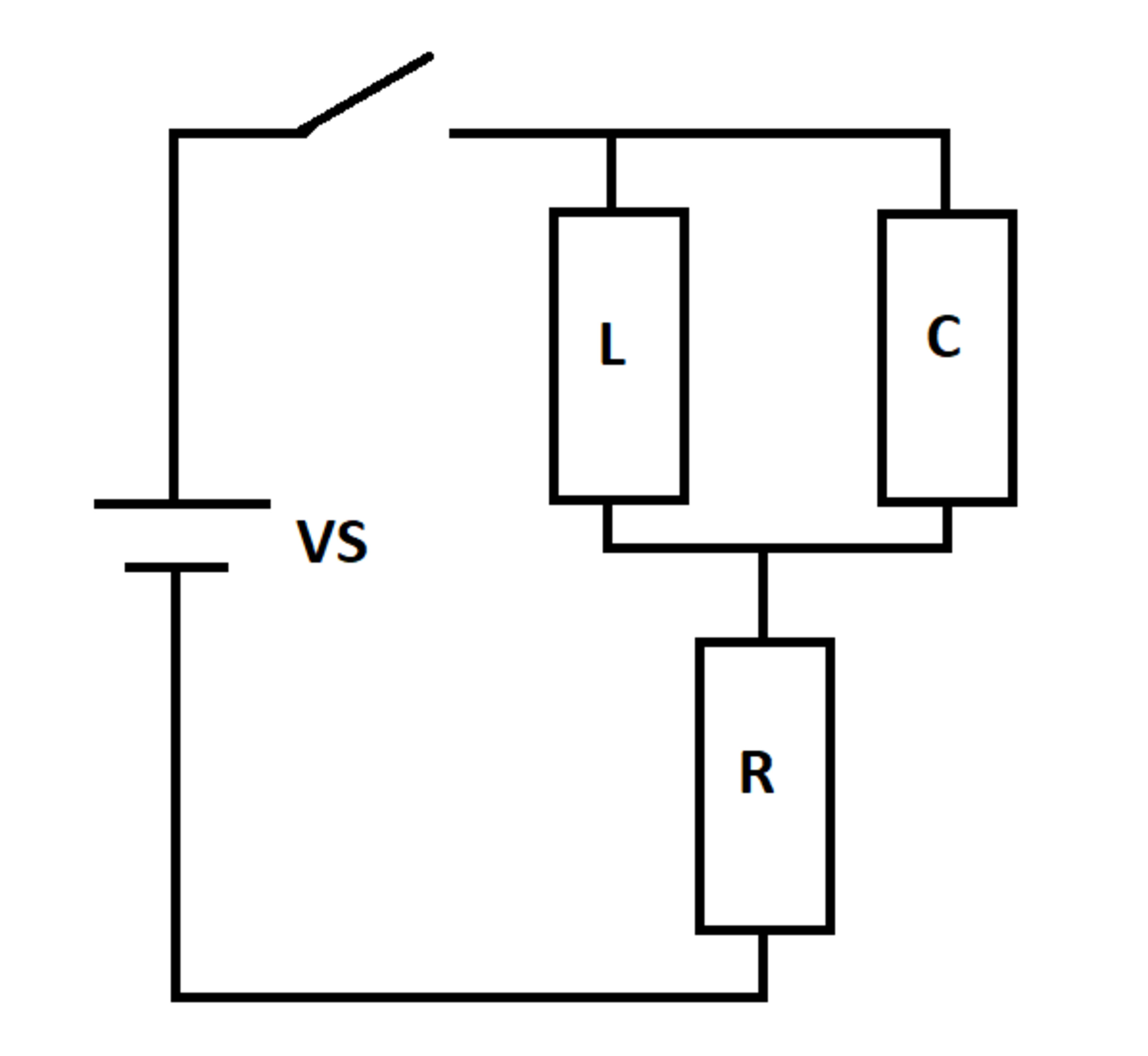
RLC Y Circuit
An RLC circuit is excited by a DC voltage source. The switch closes at time t = 0 , at which time the inductor and capacitor are de-energized.
Let I m i n and I m a x be the smallest and largest source current values over all time. Let I 0 + be the source current right after the switch closes, and let I ∞ be the steady-state source current as the elapsed time approaches infinity.
Determine the following ratio:
I 0 + + I ∞ I m i n + I m a x
Details and Assumptions:
1)
All four current values are positive numbers
2)
R
=
L
=
C
=
1
3)
V
S
=
1
0

The answer is 0.771.
This section requires Javascript.
You are seeing this because something didn't load right. We suggest you, (a) try
refreshing the page, (b) enabling javascript if it is disabled on your browser and,
finally, (c)
loading the
non-javascript version of this page
. We're sorry about the hassle.
2 solutions
@Steven Chase sir I didn't understand the logic behind the 21,22 and 37 to 41 code lines ? I think this lines have some internal relation??? Thanks in advance
A general outline of the solution. I have omitted specifics.
Applying Kirchoff's laws to the circuit gives the following relations. Note that current through the inductor is I L and that through the capacitor is I C and the charge stored in the capacitor is Q . The source current is denoted by I .
− V S + L d t d I L + I R = 0 L d t d I L − C Q = 0 d t d Q = I C I = I L + I C
By some straightforward manipulation, it can be shown that:
d t d 2 I L + d t d I L + I L = 1 0 ; d t d 2 I L = I C
Initial conditions are:
I L ( 0 ) = 0 ; Q ( 0 ) = 0 ⟹ I ˙ L ( 0 ) = 0
The closed-form solution of I L ( t ) needs to be double differentiated to get the capacitor current. Finally, the expression for source current can be obtained. It can be verified by inspecting the circuit that the source current I as soon as the switch closes and after a large amount of time is both 1 0 A . By searching (either using a computer program or by using differential calculus) for the max and min current and computing the required ratio, the answer is 0 . 7 7 1 4 .
My approach is essentially the same as the one presented by @Karan Chatrath, but with some logistical/stylistic differences. The state variables are the capacitor voltage V C and the inductor current I L .
Since the capacitor and inductor are in parallel, we have the first state-space equation:
V C = L I ˙ L I ˙ L = L V C
Then using Kirchoff's Voltage Law:
V S − V C − R ( I L + I C ) = 0 V S − V C − R ( I L + C V ˙ C ) = 0 V ˙ C = R C V S − V C − C I L
Numerical integration takes care of the rest, now that we have the rates of change of the state variables expressed in terms of the state variables and the forcing function. And finally,
I S = I L + I C = I L + C V ˙ C
The plot of source current vs. time is below. Simulation code is attached as well.