Saturating Switch
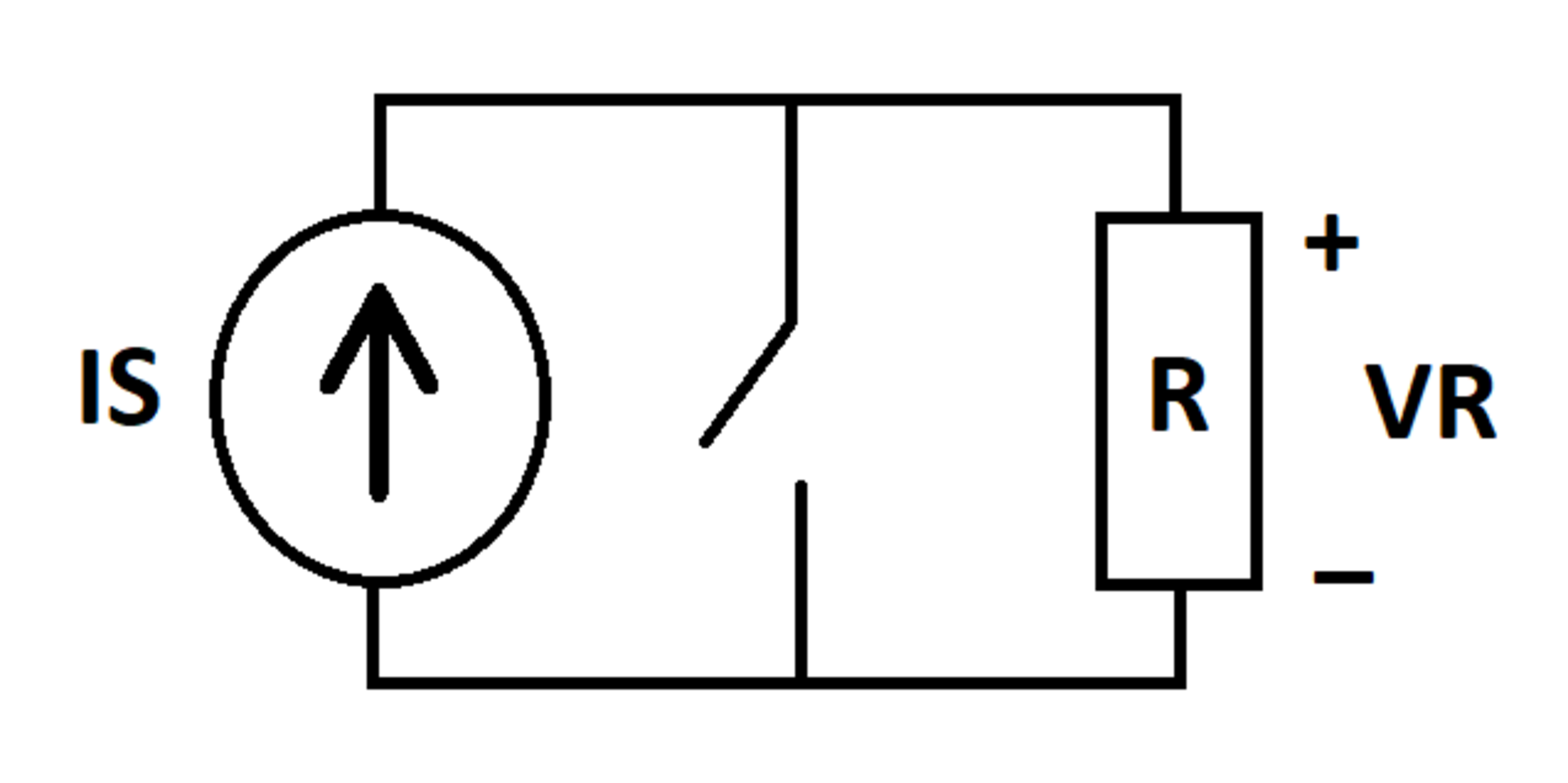
A current source outputs current into a parallel combination of a switch and a resistor . is the voltage across the resistor. Define the quantity as follows:
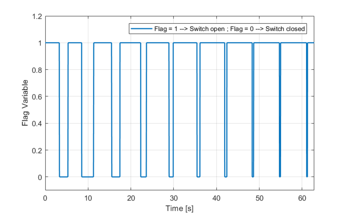
The switch is closed if either of the following two conditions is true. Otherwise, it is open.
Close Condition 1:
and
Close Condition 2:
and
Current flows into the positive terminal of the resistor. Determine the following integral:
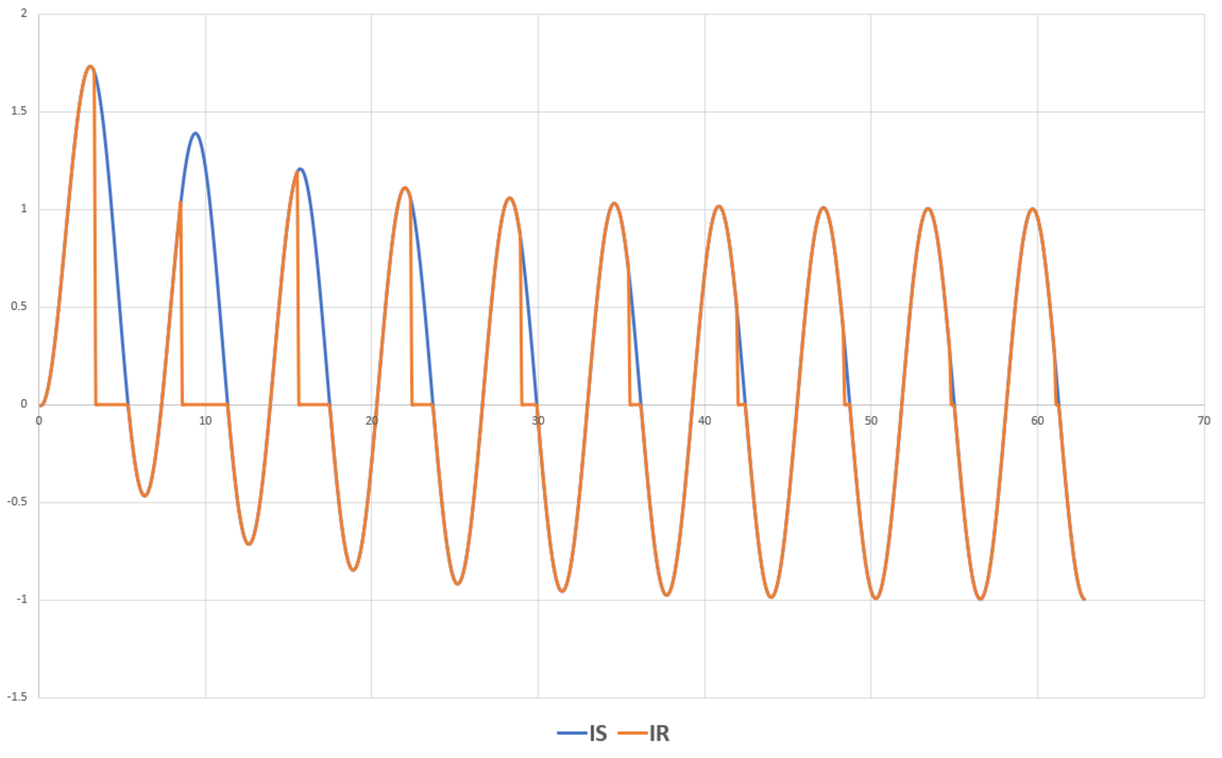
The circuit and a plot of currents and are included for reference.
Bonus: What if there was no decaying DC offset in the source current?


The answer is 7.978.
This section requires Javascript.
You are seeing this because something didn't load right. We suggest you, (a) try
refreshing the page, (b) enabling javascript if it is disabled on your browser and,
finally, (c)
loading the
non-javascript version of this page
. We're sorry about the hassle.

@Karan Chatrath has shown how to analyze this problem and derive a result. Unlike many of my problems, this one actually has a practical motivation. There is a device called a "current transformer" which is used to measure the current through some piece of apparatus (ex: the current flowing through one of the conductors of a power line). The power line conductor passes through the center of a circular iron "doughnut", and there are a number of coils of wire wrapped around the doughnut. The number of turns of wire dictates how much smaller the "secondary" current is relative to the "primary" current flowing in the transmission line.
There is typically a measurement device connected to the terminals of the wire coil, and the device has a resistance which is known as the "burden resistance". As it turns out, the iron in the doughnut limits the extent to which the current transformer output can successfully mimic the primary current. When the time integral of the burden voltage reaches a positive upper limit (dictated by the iron), the burden current can only flow provided that it does not make a positive contribution to this integral. When the time integral of the burden voltage reaches a negative lower limit, the burden current can only flow provided that it does not make a negative contribution to the integral. This phenomenon is known as "current transformer saturation", and it can be a significant concern in applications that make use of measurements from current transformers. CT saturation can be crudely modeled using a switch as outlined in this problem. There are more sophisticated ways of modeling it as well.
As for the bonus question, the CT is typically immune to saturation when the secondary current is symmetrical, provided that the current is not so large that it can saturate the CT within a half cycle. The presence of a decaying DC offset is particularly likely to cause CT saturation, since it makes an accumulating uni-polar contribution to the time integral of the burden voltage. The time constant of the decay has a big effect as well.