Self-referential circuit
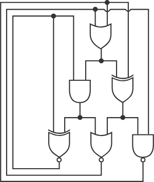
The above is a logic circuit, made up of logic gates . Each wire holds either the value true or the value false. A black dot indicates that the wires meeting at that point have the same value. The six big things are logic gates; each receives two inputs from the top side and produces a value at the bottom. The gates can be seen in the above page; note that the three bottom gates have a white dot at the bottom (their outputs are inverted).
Only one configuration of the logic circuit shown is stable. Determine this configuration. Enter your answer as a 6-digit binary number representing the output of each gate (starting from the single gate on the top row, then the two on the middle row from left to right, then the three on the bottom row from left to right), where 1 = true and 0 = false. (Leading zeros are ok.)
The answer is 110101.
This section requires Javascript.
You are seeing this because something didn't load right. We suggest you, (a) try
refreshing the page, (b) enabling javascript if it is disabled on your browser and,
finally, (c)
loading the
non-javascript version of this page
. We're sorry about the hassle.
5 solutions
Once you've looked up the symbols, the solution almost falls out naturally in the manner you explain. I think the question should include an explanation for what the gates mean even though they can be found easily. Adding this makes the problem a little more accessible to those who might see an incomprehensible problem.
Log in to reply
I tried phrasing the problem better to explain more about the logic circuit part. What each gate means is in the wiki page, so I don't think I need to completely explain it.
Here is an (abstract) algebraic approach using the
finite (Galois) field
G
F
(
2
)
(just
{
0
,
1
,
+
,
⋅
}
with mod 2 arithmetic). It gives a systematic approach to these kinds of problems. First, the logical gate operators can be formed as algebraic expressions in operators, constants, and variables
x
,
y
in
G
F
(
2
)
.
NOT
x
=
1
+
x
,
x
AND
y
=
x
y
,
x
XOR
y
=
x
+
y
,
x
OR
y
=
x
+
y
+
x
y
.
Next, assign gate output variables
{
b
n
}
n
=
0
,
…
,
5
∈
G
F
(
2
)
as shown in the figure. As per the circuit diagram,
equate the logical gate outputs based on the inputs to the assigned output variables
to produce the following system of equations:
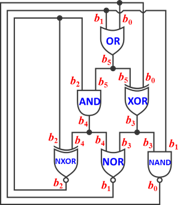
( 0 ) ( 1 ) ( 2 ) ( 3 ) ( 4 ) ( 5 ) b 0 = 1 + b 1 b 3 , b 1 = 1 + b 3 + b 4 + b 3 b 4 , b 2 = 1 + b 2 + b 4 , b 3 = b 0 + b 5 , b 4 = b 2 b 5 , b 5 = b 0 + b 1 + b 0 b 1 .
Solve by using G F ( 2 ) ’s multiplicative idempotency ( x 2 = x ) and additive nilpotency ( x + x = 0 ) for simplification (along with its other props).
Add b 2 to both sides of (2): b 2 + b 2 = b 2 + 1 + b 2 + b 4 ⟺ 0 = 0 + 1 + b 4 . Add 1 to both sides: 1 + 0 = 1 + 1 + b 4 ⟺ 1 = b 4 ∴ b 4 = 1 .
Sub b 4 into (1): b 1 = 1 + b 3 + b 4 + b 3 b 4 = 1 + b 3 + 1 + b 3 ⋅ 1 = ( 1 + 1 ) + ( b 3 + b 3 ) = 0 + 0 = 0 ∴ b 1 = 0 .
Multiply (1) by b 3 : b 3 b 1 = b 3 ⋅ 1 + b 3 2 + b 3 b 4 + b 3 2 b 4 = ( b 3 + b 3 ) + ( b 3 b 4 + b 3 b 4 ) = 0 + 0 = 0 ∴ ( 6 ) b 1 b 3 = 0 . Sub (6) into (0): b 0 = 1 + b 1 b 3 = 1 + 0 = 1 ∴ b 0 = 1 .
Sub b 0 and b 1 into (5): b 5 = b 0 + b 1 + b 0 b 1 = 1 + 0 + 1 ⋅ 0 = 1 + 0 + 0 = 1 ∴ b 5 = 1 .
Sub b 0 and b 5 into (3): b 3 = b 0 + b 5 = 1 + 1 = 0 ∴ b 3 = 0 .
Sub b 4 and b 5 into (4): b 4 = b 2 b 5 ⟺ 1 = b 2 ⋅ 1 = b 2 ∴ b 2 = 1 .
Therefore, b 5 b 4 b 3 b 2 b 1 b 0 = 1 1 0 1 0 1 2 = 5 3 1 0 .
Not as elegant, but a truth table approach...
Let ABC be three inputs top to bottom, outputs 1 to 6 from the outputs of the gates in order top to bottom, left to right
By reversing 4 to 6 so their outputs match AtoC we see only 101 input matches 101 output so the coded answer is the middle six bits.
ABC 123456 654
000 000111 111
001 000010 010
010 101100 001
011 111100 001
100 100111 111
101 110101 101 in=out
110 100111 111
111 110101 101
Answer = 110101
If we rename the gates according to their positions top to bottom first, then left to right by the row, then the we'll have an OR A, AND B, XOR C, XNOR D, NOR E and NAND F.
A = E + F
B = A × D
C = F 🔀 A
D = –( D 🔀 B )
E = –( B + C )
F = –( C × E )
Let's look at D, since it's one of the special self-made gate. As an XNOR gate, it will outputs 1 for the same inputs and outputs 0 for different inputs. Therefore, the only possible B in both cases is B = 1. Then, AND B can only have A = D = 1 as inputs itself, while at the same time will influence NOR E to be 0. E = 0 would need F = 1 as an input pair in a positive OR A, and C = 1 🔀 1 = 0 is the final output that we need here.
Answer = 110101
One way to solve can be to start from the bottom of the circuit and call the 3 outputs as x , y and z . Then if we feed y and z (as per circuit) to first gate which is the OR / addition gate. We get
Output 1= y+z
Output 2= x(y+z)
Output 3= yz'
Output 4 = x'+xy+xz which is also equal to x
Output 5 = x'y'+x'z+y'z' which is also equal to y
Output 6 = y'+z which is also equal to z
Thus we get 3 equations and starting with y'+z = z we see that there are 2 possible solutions,
1) y=1 and z either 0 or 1. But with this the output 4 equation gives x=1 but then equation 5 is not satisfied.
2) y=0 and z=1. In this case we get from output 4 that x=1 and the output 5 is satisfied. Thus x=1, y=0, z=1. Hence Output 1 = 1, Output 2 = 1 and Output 3 = 0.
Thus the answer will be 1,1,0,1,0,1.
This is a more "real" version of the previous edition , now actually saying what you need to do. However, it's also easier than that: there are only three outputs at the bottom, so we can try all 2 3 = 8 combinations and feed them through the circuit to check which one works.
But let's actually solve this thing in a more interesting fashion. Call the outputs of the gates A , B , C , D , E , F in the same order as they are asked in the answer. Let ⋅ , + , ⊕ be AND, OR, XOR gates respectively, and x as negation of x . Let 1 stands for true and 0 stands for false. The equations are:
Note that x = x ⊕ 1 , so the fourth equation can be rewritten as D ⊕ 1 = D ⊕ B . But we can cancel like terms in XOR (or otherwise XOR both sides with D ), so we get B = 1 .
And that's all the hard work. Feeding B = 1 to the second equation, we get A = D = 1 (the only way to make an AND to give 1). Feeding B = 1 to the fifth equation, we get E = 0 (because B + C = 1 no matter what C is). From the first equation, since A = 1 and E = 0 , the only way to satisfy it is F = 1 . Since we now have A = F = 1 , we can plug it in to the third equation to give C = 0 . We can verify all equations are satisfied with this assignment: ( A , B , C , D , E , F ) = ( 1 , 1 , 0 , 1 , 0 , 1 ) . Thus that's our answer, 1 1 0 1 0 1 .