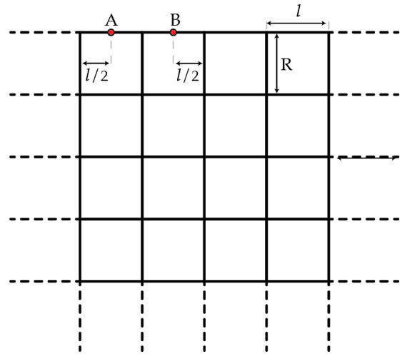
Semi-infinite grid
Suppose we build a semi-infinite grid with square cells as shown in the figure below. Each wire has a length
l
and a resistance of
r
=
1
Ω
. What is the equivalent resistance between the points A and B?

The answer is 0.75.
This section requires Javascript.
You are seeing this because something didn't load right. We suggest you, (a) try
refreshing the page, (b) enabling javascript if it is disabled on your browser and,
finally, (c)
loading the
non-javascript version of this page
. We're sorry about the hassle.
3 solutions
Suppose C is the middle point of AB.
Imagine there is a current I start at A, go through the grid to the infinity. Because of the symmetry of the grid, we have I A C = 2 I and I C B = 4 I .
Imagine there is a current -I start at B, go through the grid to the infinity. Because of the symmetry of the grid, we have I A C = 4 I and I C B = 2 I .
Add two cases together, we have a current I start at A, go through the grid and end at B.
We also have I A C = I C B = 4 I + 2 I = 4 3 I .
We have I R A B = U A B = 2 R ( I A C + I C B ) = 4 3 I R .
Therefore, R A B = 4 3 R .
Ability to upload images would have reduced the number of words used.
Main ideas are principles of superposition and symmetry of the grid.
First apply a voltage of V / 2 to the point A. We can assume that points on the grid at infinity are grounded and are at zero potentia. Let the current through the point A be I . Now let us study the current flow patterns.
-
Equal currents I / 2 flow out in either directions of A up to the nearest nodes on the upper edge of the grid.
-
Observe that no current can flow on all the horizontal wires that are directly below the point A, again by symmetry. So the situation is like two disconnected "quarter-infinite" grids to the left and right of A, whose corners are the ends of the wire segment containing point A.
-
As current I / 2 reaches the two ends of the wire segment containing the point A, current divides equally in to I / 4 each on horizontal and vertical wire segments, again by symmetry. To understand this better, think of current flowing into the corner of the "quarter-infinite" grid as mentioned in the point above.
-
So the current flowing in the segment containing point B is I / 4 .
Now consider another situation in which, we apply a potential of − V / 2 to point B. Now all the currents are reversed and a current I flows out through point B.
Superpose these two situations to get the actual current distribution through the grid.
Thus, when a voltage of
V
/
2
is applied to the point A and
−
V
/
2
at point B, current through the segment from point A to point B is
2
I
+
4
I
=
4
3
I
The potential difference between the points, A and B,
V
A
B
=
V
/
2
−
(
−
V
/
2
)
=
V
is related to the current by
V
=
4
3
I
r
.
Thus equivalent resistance is
R
e
q
=
I
V
=
4
3
r
=
0
.
7
5
Ω
.
Reference: This technique of symmetry and superposition was hinted in one of the "Supplementary Problems" in the book by Purcell, Electricicity and Magnetism, 1st Edition. There the problem was to find the equivalent resistance between two adjacent nodes in an infinite grid.
You can use

format to upload images in your solution.
Sir can u please share the link of the above book
Consider a current of 1 A applied at the point A , grounding at infinity. By symmetry it is clear that currents of 2 1 A flow in each direction away from A , and moreover that the current in any horizontal wire directly below A is zero. Thus we can effectively remove these middle wires.
Putting together the current pictures for a current of 1 A applied at A , and a current of − 1 A applied at B , we see that there is a current of 4 3 A flowing along the horizontal wire from A to B (and no current flows in the vertical wire that meets this wire at the node halfway between A and B . The wire from A to B has resistance 1 Ω , and hence there is a potential difference of 4 3 V between A and B . This potential difference has been obtained by applying a 1 A current in and out of the grid of resistors at A and B , and hence the effective resistance of this grid between A and B is 4 3 Ω .